
Troubleshooting guide

11-7
ATM and Layer 3 Switch Router Troubleshooting Guide
OL-1969-01
Chapter 11 Troubleshooting Layer 3 Network Connections
Overview of Layer 3 Switching
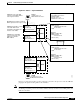
If the destination MAC address is a broadcast address (FFFF.FFFF.FFFF), the packet is tagged with the
destination set as all ports in that bridge group, and it is sent out to the switching fabric. The fabric ASIC
creates a pointer from that point in the memory to all ports in that bridge group. For example, if there
were eight ports in a bridge group, all eight ports would receive that broadcast.
How MAC Addresses are Learned by the Switch
The following steps describe the MAC address learning process used by the switch router.
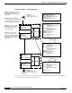
Step 1 When a port receives a packet with an unknown source and destination MAC address, it stores the source
address as “locally learned” and forwards the packet, as an “unknown unicast,” to all ports in the bridge
group (similar to a broadcast).
Step 2 The receiving port also sends a LightStream InterProcess Communication (LSIPC) message to the route
processor to allow it to update the bridging table on the route processor.
Note This bridging table in the route processor is only used to allow you check the learned MAC addresses
using the show bridge command.
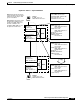
Step 3 All ports in the bridge group receive a copy of the “unknown unicast” and forward the packet.
Step 4 The receiving ports learn the new source address of the packet as a “remote entry.”
Step 5 These receiving ports determine which interface sent the packet, based on the VPI and VCI header that
points to a P2MP leaf, and the port already knows the corresponding P2MP root.
Step 6 Now all ports in the bridge port have learned the new source MAC address.
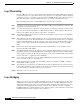
Step 7 The destination station for that frame responds.
Step 8 The port that receives the response learns the MAC address of the destination station (now the source
address in the response). It has already learned the destination address, allowing it to forward the packet
to the correct port.
Step 9 Only that egress port will then learn the new source address.
Step 10 The route processor is also notified of the new destination station source MAC address.
Step 11 Layer 2 switching then occurs between the two ports.
Note After 5 minutes of inactivity, MAC addresses are deleted from the CAM. The port sends another
message to the route processor to remove the MAC from the bridging table.
After both the source and the destination MAC address have been learned, the following procedure
occurs during Layer 2 frame switching:
Step 1 A packet is received at the physical interface. The CEFA ASIC provides the MAC-layer functions, and
the packet is stored in internal memory.
Step 2 As soon as the first 64 bytes of the frame are read, the microcode running on the microcontroller reads
the MAC source and destination addresses. If the destination MAC address is not that of the interface,
Layer 2 switching is required. This information can now be used by the search engine.