
Troubleshooting guide

11-6
ATM and Layer 3 Switch Router Troubleshooting Guide
OL-1969-01
Chapter 11 Troubleshooting Layer 3 Network Connections
Overview of Layer 3 Switching
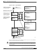
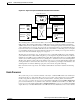
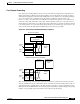
Layer 3 Forwarding
By using CEF, each of the line cards maintains a Forwarding Information Base (FIB) table downloaded
from the switch processor. Any changes made to the route processor routing table, caused by additions
or deletions of routes or route flaps, are updated in the central FIB, which in turn updates the line card
FIBs. This means that, at all times, all line cards have a correct map of the network topology.
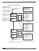
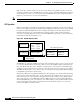
Packet switching in the Layer 3 enabled ATM switch router takes place as follows:
Step 1 A packet is received at the physical interface. The CEFA ASIC provides the MAC-layer functions, and
the packet is stored in internal memory.
Step 2 As soon as the first 64 bytes of the frame are read, the microcode running on the microcontroller reads
the source and destination IP addresses, or IPX network information. If the destination MAC address
belongs to the switch router, the packet is routed. If not, it is bridged.
Step 3 The destination IP address information is used by the search engine to begin a lookup, in the CAM table,
for the longest match entry.
Step 4 The destination network is matched within 64 clocks (or approximately 2.5 microseconds). The match
is returned to the microcontroller, which in turn moves the frame from the internal memory to the Fabric
Interface frame FIFO buffer. At the same time, the search engine returns relevant information such as
quality of service (QoS) classifications, and MAC header rewrite information, to the Control FIFO
buffer.
Step 5 Packet rewrite and QoS classifications take place at the input Ethernet processor interface or Cisco
Express Forwarding ASIC (CEFA).
Step 6 The VPI and VCI are attached at the beginning of the packet. The VPI and VCI used corresponds to the
particular QoS being requested. The packet then goes through the SAR (Segmentation and Reassembly),
which segments the packet into 48-byte payloads. The previously retrieved VPI and VCI-value is written
into the cell header to complete the 53-byte ATM Cell.
Step 7 As soon as the entire frame is received into the Frame FIFO buffer, the frame moves into the shared fabric
and is stored with a pointer to the output port.
Step 8 If that output interface is currently busy transmitting a frame, the scheduler uses WRR to determine
which packet should be sent next.
Step 9 The destination port is signaled, by the switching-fabric ASIC, to take the frame out of a known memory
location. The destination port knows that it is receiving the correct frame because of the internal routing
tag corresponding to a particular, internal, port-to-port circuit.
Step 10 The frame is sent out to the network.
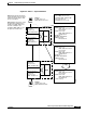
Layer 2 Bridging
When a port or group of ports are running in bridging mode, the search engine initiates a lookup, in the
CAM table, based on the Layer 2 MAC address. Because the Layer 3 enabled ATM switch router is a
distributed switching system, each port (or in this case, CEFA) maintains a list of addresses and ports of
exit that are of local significance. For example, if Address A is a destination learned on interface
FastEthernet 0/0/1, the remaining interfaces on the switch do not have to have that address stored in their
CAM tables unless they have a packet to send to Address A.