
Troubleshooting guide

11-5
ATM and Layer 3 Switch Router Troubleshooting Guide
OL-1969-01
Chapter 11 Troubleshooting Layer 3 Network Connections
Overview of Layer 3 Switching
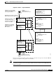
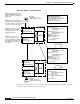
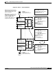
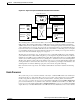
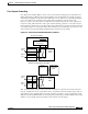
Figure 11-3 Phase 3 — Layer 3 Packet Flow
ARP Request Packet:
Source MAC: 00:10:e3:aa...
Destination MAC: 00:90:21:bb...
Source IP:172.1.1.5
Destination IP: 172.1.3.10
Ingress Interface Route Table:
IP Add: 172.1.1.5
MAC Add: 00:10:e3:aa...
IF: Fa 3/0/0
IP Add: 172.1.3.10
MAC Add: 00:90:21:cc...
IF:Giga 9/1/0
MySubnet:
My MAC: 00:90:21:bb...
IF-Map: Fa 3/0/0
Broute VC-79
...
Central CPU Route Table:
IP Add: 172.1.1.5
MAC Add: 00:10:e3:aa...
IF: Fa 3/0/0
IP Add: 172.1.3.10
MAC Add: 00:90:21:cc...
IF:Giga 9/1/0
MySubnet:
My MAC: 00:90:21:bb...
IF-Map: Fa 3/0/0
Broute VC-79
...
Host A
IP Add: 172.1.1.5
MAC Add: 00:10:e3:aa...
Egress Interface:
Giga 9/1/0
IP: 172.1.2.2
MAC: 00:90:21:cc...
CPU
Ingress Interface:
Giga 1/0/0
IP: 172.1.2.5
MAC: 00:90:21:dd...
Egress Interface:
Fast 2/1/5
IP: 172.1.3.8
MAC: 00:90:21:ee...
Host B
IP Add: 172.1.3.10
MAC Add: 00:01:02:ff...
C8540CSR-1
C8540CSR-2
CPU
Ingress Interface:
Fast 3/0/0
IP: 172.1.1.8
MAC: 00:90:21:bb...
Step 8: All subsequent packets
received from Host A are Layer 3
switched using the ingress and
egress route tables.
Copy
Other Interface Route Tables:
IP Add: 172.1.1.5
MAC Add: 00:10:e3:aa...
IF: Fa 3/0/0
IP Add: 172.1.3.10
MAC Add: 00:90:21:cc...
IF: Giga 9/1/0
...(other routes)
49956
Step 9: When the packets reach
the destination switch ingress
interface the MAC address for
Host B is rewritten to the
destination MAC address and
the packets are delivered.