
Troubleshooting guide

11-4
ATM and Layer 3 Switch Router Troubleshooting Guide
OL-1969-01
Chapter 11 Troubleshooting Layer 3 Network Connections
Overview of Layer 3 Switching
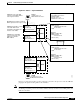
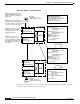
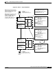
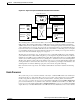
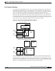
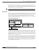
Figure 11-2 Phase 2 — Layer 3 Packet Flow
Figure 11-3 shows and describes, in Steps 8 and 9, how subsequent packets sent by Host A, to Host B,
are switched without the help of the route processor.
ARP Request Packet:
Source MAC: 00:10:e3:aa...
Destination MAC: 00:90:21:bb...
Source IP: 172.1.1.5
Destination IP: 172.1.3.10
Ingress Interface Route Table:
IP Add: 172.1.1.5
MAC Add: 00:10:e3:aa...
IF: Fa 3/0/0
IP Add: 172.1.3.10
MAC Add: 00:90:21:cc...
IF: Giga 9/1/0
MySubnet:
My MAC: 00:90:21:bb...
IF-Map: Fa 3/0/0
Broute VC-79
...(other routes)
Central CPU Route Table:
IP Add: 172.1.1.5
MAC Add: 00:10:e3:aa...
IF: Fa 3/0/0
IP Add: 172.1.3.10
MAC Add: 00:90:21:cc...
IF: Giga 9/1/0
MySubnet:
My MAC: 00:90:21:bb...
IF-Map: Fa 3/0/0
Broute VC-79
...(other routes)
Copy
Host A
IP Add: 172.1.1.5
MAC Add: 00:10:e3:aa...
Egress Interface:
Giga 9/1/0
IP: 172.1.2.2
MAC: 00:90:21:cc...
CPU
Ingress Interface:
Giga 1/0/0
IP: 172.1.2.5
MAC: 00:90:21:dd...
Egress Interface:
Fast 2/1/5
IP: 172.1.3.8
MAC: 00:90:21:ee...
Host B
IP Add: 172.1.3.10
MAC Add: 00:01:02:ff...
C8540CSR-1
C8540CSR-2
CPU
Ingress Interface:
Fast 3/0/0
IP: 172.1.1.8
MAC: 00:90:21:bb...
Step 5: Host A adds the ingress
If the Search Engine
interface MAC address to the
packet and starts sending to the
destination.
Step 7: The CPU sends an
ARP request to the network
does not find the next hop address,
it sends an ARP to learn it. This ARP
request is only performed once.
searching for the Host B
destination network.
Step 6:
Step 8: The source CPU
receives the ARP response
from the destination network
and updates the central route
table and all of the interface
route tables.
Copy
Other Interface Route Tables:
IP Add: 172.1.1.5
MAC Add: 00:10:e3:aa...
IF: Fa 3/0/0
IP Add: 172.1.3.10
MAC Add: 00:90:21:cc...
IF:
49955
...(other routes)