
Troubleshooting guide

10-40
ATM and Layer 3 Switch Router Troubleshooting Guide
OL-1969-01
Chapter 10 Troubleshooting Ethernet, ATM Uplink, and POS Uplink Interfaces
Troubleshooting ATM Uplink with Enhanced Gigabit Ethernet Interface Modules
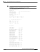
• c3— The value extracted from the SONET path signal label byte (C2)
• S1—(1 byte) Synchronization status byte
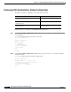
Step 10 Check the Content of Path trace field. The path trace buffer is used to communicate information
regarding the remote hostname, interface name/number, and IP address. This is a Cisco-proprietary use
of the J1 (path trace) byte.
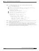
Step 11 Check the Active defects field. It indicates the currently configured alarms with defects and is a primary
troubleshooting indicator.
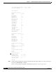
Step 12 Check the Alarm reporting enabled field—It is a list of alarms for which you enabled reporting by
entering the pos report interface command.
Step 13 Check the Active Defects field—It is a list of all currently active defects.
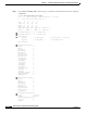
Step 14 Check the OC12 Counters field. If this number is incrementing, this indicates a problem in the network.
Check for any BIP(B1)/BIP(B2)/BIP(B3) (Bit interleaved parity) error reported.
• For B1, the bit-interleaved parity error report is calculated by comparing the BIP-8 code with the
BIP-8 code extracted from the B1 byte of the following frame. Differences indicate that section-level
bit errors have occurred.
• For B2, the bit-interleaved parity error report is calculated by comparing the BIP-8/24 code with the
BIP-8 code extracted from the B2 byte of the following frame. Differences indicate that line-level
bit errors have occurred.
• For B3, the bit-interleaved parity error report is calculated by comparing the BIP-8 code with the
BIP-8 code extracted from the B3 byte of the following frame. Differences indicate that path
level-bit errors have occurred.
Check the FEBE (Far end block errors).
• Line far-end block errors (accumulated from the M0 or M1 byte) are reported when the downstream
LTE detects BIP(B2) errors.
• Path far-end block errors (accumulated from the G1 byte) are reported when the downstream PTE
detects BIP(B3) errors.
Step 15 Check the OC12 error secs field. This field shows the total seconds where there were one or more alarms
since the switch was rebooted.
Check AIS (Alarm indication signal).
• The line alarm indication signal is sent by the section terminating equipment (STE) to alert the
downstream line terminating equipment (LTE) that an LOS or LOF defect has been detected on the
incoming SONET section.
• The path alarm indication signal is sent by the LTE to alert the downstream path terminating
equipment (PTE) that it has detected a defect on its incoming line signal.
Check RDI (Remote defect indication).
• The line remote defect indication is reported by the downstream LTE when it detects LOF, LOS, or
AIS.
• The path remote defect indication is reported by the downstream PTE when it detects a defect on the
incoming signal.
Step 16 Check the OC12 error free secs field. It indicates the number of seconds since the last error.
Step 17 Check the BER thresholds field. It is a list of bit error rate (BER) thresholds that have been crossed.
Step 18 Check the TCA thresholds field. It is a list of threshold crossing alarms (TCA).