
Troubleshooting guide

10-39
ATM and Layer 3 Switch Router Troubleshooting Guide
OL-1969-01
Chapter 10 Troubleshooting Ethernet, ATM Uplink, and POS Uplink Interfaces
Troubleshooting ATM Uplink with Enhanced Gigabit Ethernet Interface Modules
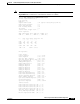
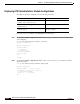
Slicer Transmit Counters:
Cells =0
Frames =0
Status Registers:
Rx_gmac_status =00000000
Tx_gmac_status =00000000
Rx_slicer_status =00000003
Tx_slicer_status =00000000
Interface Configuration Mode:
ATM clock line; STS-12c; Line is admin shutdown
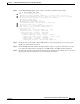
Sonet overhead:
k1/k2 = 0/6
s1s0 = 00, c2 = 0xCF, s1 = 0x0
Contents of Section trace buffer:
LLLLLLLLLLLLLLLLLLLLLLLLLLLLLLLLLLLLLLLLLLLLLLLLLLLLLLLLLLLLLLLL
Contents of Path trace buffer:
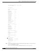
Active Defects: None
Alarm reporting enabled for: SF SLOS SLOF B1-TCA B2-TCA PLOP B3-TCA
Active ATM Payload Defect: LCD-P
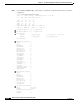
OC12 counters:
b1 - # section BIP-8 errors
b2 - # line BIP-8 errors
b3 - # path BIP-8 errors
ocd - # out-of-cell delineation errors - not implemented
g1 - # path FEBE errors
z2 - # line FEBE errors
chcs - # correctable HEC errors
uhcs - # uncorrectable HEC errors
b1:0, b2:0, b3:0, ocd:0
g1:0, z2:0, chcs:0, uhcs:0
OC12 errored secs:
b1:0, b2:0, b3:0, ocd:0
g1:0, z2:0, chcs:0, uhcs:0
lineAIS:0, lineRDI:0, pathAIS:0, pathRDI:0
OC12 error-free secs:
b1:0, b2:0, b3:0, ocd:0
g1:0, z2:0, chcs:0, uhcs:0
phy_tx_cnt:0, phy_rx_cnt:0
BER thresholds: SF = 10e-0 SD = 10e-0
TCA thresholds: B1 = 10e-6 B2 = 10e-6 B3 = 10e-6
Switch#
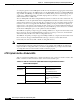
Step 8 Check the Interface Configuration Mode field. This field indicates the clock configuration and the
administrative status of the interface.
Step 9 Check Sonet Overhead fields. These fields indicate the following:
• k1/k2—used for Automatic Protection Switching (APS)
• s1s0—(2 bits) not used by SONET, may need to be configured for SDH