
Troubleshooting guide


10-34
ATM and Layer 3 Switch Router Troubleshooting Guide
OL-1969-01
Chapter 10 Troubleshooting Ethernet, ATM Uplink, and POS Uplink Interfaces
Troubleshooting ATM Uplink with Enhanced Gigabit Ethernet Interface Modules
An example application of the ATM uplink is traffic from a LAN switch being aggregated at the Catalyst
8540 CSR and then passed to the ATM network over the ATM uplink. The Layer 3 enabled ATM uplink
supports RFC 1483 (Multiprotocol Encapsulation over ATM), which provides for the mapping of Layer
3 addresses to ATM virtual circuits, and traffic shaping. Refer to the Guide to ATM Technology for
additional information on RFC 1483.
The two ATM uplink with enhanced Gigabit Ethernet interface modules are the OC-3c and the OC-12c.
The ATM OC-3c or OC-12c uplink with enhanced Gigabit Ethernet interface modules consist of two port
adapters that are attached to a carrier module. The port adapters are not hot-swappable, but the interface
module as a whole is hot-swappable. The ATM OC-3c uplink port adapter or the OC-12c uplink port
adapter resides on the left side of the interface module, and the one-port enhanced Ethernet Gigabit port
adapter resides on the right side. This combination provides an Ethernet port for connection to, or within,
a LAN and an ATM uplink port to a metropolitan-area network (MAN).
The ATM OC-3c uplink port adapter supports 155-Mbps multimode or single-mode intermediate-reach
fiber connections. It supports Fast EtherChannel operation, uses SC-type connectors, and has built-in
ACL functionality. The OC-3c has 64K of routing table memory.
The ATM OC-12c uplink port adapter supports 622-Mbps multimode or single-mode intermediate-reach
fiber connections. It supports Fast EtherChannel, SC-type connectors, and has built-in ACL
functionality. The OC-12c has 64K or 256K of routing table memory.
Note The port adapters within the ATM OC-12c or OC-3c uplink with enhanced Ethernet interface
modules must have matching routing table memory. As an example, if the ATM OC-12c uplink port
adapter has 64K of routing table memory, the enhanced Gigabit Ethernet port adapter must have 64K
of routing table memory for the interface module to function properly.
ATM Uplink Interface Module LEDs
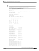
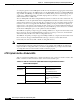
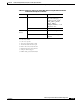
Table 10-6 describes the LEDs used to confirm and troubleshoot the operation of interface modules. The
LEDs on interface modules indicate the status of the modules and their ports.
Table 10-6 ATM OC-3c and OC-12c Uplink With Enhanced Gigabit Ethernet Interface
Module LED Descriptions
LED State Description
Tx
(Transmit)
Green Port is transmitting a
packet. Green for
approximately 50 ms.
Off No signal is detected.
Rx (Receive) Green Port is receiving a packet.
Green for approximately
50 ms.
Off No signal is detected.