
Troubleshooting guide


10-27
ATM and Layer 3 Switch Router Troubleshooting Guide
OL-1969-01
Chapter 10 Troubleshooting Ethernet, ATM Uplink, and POS Uplink Interfaces
Troubleshooting Gigabit Ethernet Interface Modules
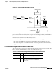
Figure 10-2 Enhanced Gigabit Ethernet Block Diagram
The enhanced Gigabit Ethernet interface module uses the Gigabit processor interface (XPIF) with a
faster external search engine that has a Cisco Systems proprietary FPGA and Ternary CAM (TCAM) to
provide the search engine for the Layer 3 routing and Layer 2 switching functionality.
The Gigabit Ethernet interface module with the Gigabit processor interface is used with all of the
interface modules described in the troubleshooting sections:
• Troubleshooting Two-Port Enhanced Gigabit Ethernet Interface Modules, page 10-26
• Troubleshooting ATM Uplink with Enhanced Gigabit Ethernet Interface Modules, page 10-33
• Troubleshooting Packet-over-SONET Uplink with Enhanced Gigabit Ethernet Interface Modules,
page 10-41
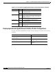
Two-Port Enhanced Gigabit Ethernet Interface Module LEDs
Table 10-5 describes the LEDs used to confirm and troubleshoot the operation of interface modules. The
LEDs on interface modules indicate the status of the modules and their ports.
Switching
Database
Search
Engine
Memory
Access Unit
GMAC
SAR
PHY/GBIC
To Gigabit Ethernet
Micro
Controller
Statistics
TCAM FPGA
To Switch Fabric
Packet
Transform
Engine
XPIF
(Gigabit Ethernet
Processor Interface)
51541
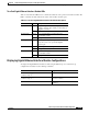
Table 10-5 Two-Port Enhanced Gigabit Ethernet Interface Module LED Descriptions
LED State Description
Link Green A port is operational (a signal is detected).
Off No signal is detected.
Full-Duplex On A port is operating in full-duplex mode. This is
always the case for an operational Gigabit
Ethernet port.