
Troubleshooting guide

10-24
ATM and Layer 3 Switch Router Troubleshooting Guide
OL-1969-01
Chapter 10 Troubleshooting Ethernet, ATM Uplink, and POS Uplink Interfaces
Troubleshooting Gigabit Ethernet Interface Modules
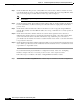
Follow these steps to troubleshoot the status of a Gigabit Ethernet interface module:
Step 1 Use the show controllers GigabitEthernet card/subcard/port command to check the configuration.
Note The Catalyst 8540 CSR has no switch feature card. Consequently, you can not check the number of
cells switched on an individual VC.
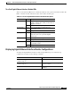
Switch# show controllers gigabitEthernet 10/0/0
IF Name: GigabitEthernet10/0/0
Port Status UP
FPGA Rev : 0.4
Gigabit Ether Status : 0xFDE7(Optical Detect,Rx Sync,Link Up)
Mode Parallel Register : 0x0
Port 0 Serial Mode Register : 0x0
Port 1 Serial Mode Register : 0x0
Link Interrupt Enable : 0x1
Tx Disable : 0x0
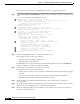
Slicer registers
SMDR 0x0060 (Tx En,Rx En)
SSTR 0x1000
EVER 0x1704 (C1)
SSMR 0x4000 SIMR 0x0000 MBXW 0x0000 MBXR 0x0000
SPER 0xF000 GMUX VER 0x17B1 MARKER 0x17B1
MAC registers
CMCR : 0x00000423 (Tx Enabled,Rx Enabled,Half)
CMPR : 0x140A0E61
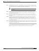
MII registers:
Control Register (0x0): 0x1140
Status Register (0x1): 0x16D
Auto Neg. Advt. Register (0x4): 0x20
Auto Neg. Partner Ability Reg (0x5): 0x0
RX Configuration Register (0xA): 0x17
TR_IPG_TIME Register (0x10): 0x3
PAUSE_TIME Register (0x11): 0x0
PAUSE_SA1 Register (0x12): 0x0
PAUSE_SA2 Register (0x13): 0x0
PAUSE_SA3 Register (0x14): 0x0
Pause Watermark Register (0x15): 0xC040
TX FIFO Watermark Register (0x16): 0xFF02
PAUSE_STAT_SENT Register (0x17): 0x0
PAUSE_STAT_RCVD Register (0x18): 0x0
Memory Address Register (0x19): 0x0
Memory Control Register (0x1A): 0x1
Memory Data High Register (0x1B): 0x0
Memory Data Low Register (0x1C): 0x0
Sys Control Register (0x1E): 0x70C
Sys Status Register (0x1F): 0x80
Link Status Register [3-0]|[7-4]: 0x1|0x0
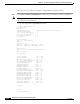
Counters :
Channel 0:
MAC Receive Counters: