
Troubleshooting guide

10-20
ATM and Layer 3 Switch Router Troubleshooting Guide
OL-1969-01
Chapter 10 Troubleshooting Ethernet, ATM Uplink, and POS Uplink Interfaces
Troubleshooting Gigabit Ethernet Interface Modules
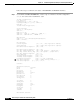
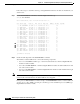
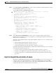
Figure 10-1 is a block diagram of the eight Gigabit Ethernet port interface module, and shows how the
interface communicates with the route processor and switch fabric across the backplane.
Figure 10-1 Eight Gigabit Ethernet Port Interface Block Diagram
Eight-Port Gigabit Ethernet Interface Module LEDs
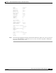
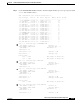
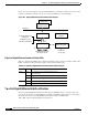
Table 10-3 describes the LEDs used to confirm and troubleshoot the operation of interface modules. The
LEDs on interface modules indicate the status of the modules and their ports.
Two-Port Gigabit Ethernet Interface Modules
The two-port Gigabit Ethernet interface module supports 1000-Mbps Layer 2 or Layer 3 fiber-optic
connections. It provides two Gigabit Ethernet ports that have GBIC modular transceivers and SC-type
fiber connectors. The two-port Gigabit Ethernet interface module is available with
16K or 64K of memory. Routing tables use this memory.
Switch fabric
CPU
(Route processor)
EPIFs PAM Bus
interface
Switch subsystem GECPU
(R5K subsystem)
8 Gigabit Ethernet ports
(Front-panel ports
Front-panel
console port
P3
P0
Backplane
P1
P10
2 Gigabit aggregated
trunk port
(Backplane ports)
802.1Q encapsulation
50432
Table 10-3 Eight-Port Gigabit Ethernet Interface Module LED Descriptions
LED State Description
Status Green The system has passed internal self-tests and
diagnostic tests.
Red The system has failed internal self-tests and diagnostic tests.
Orange The system is booting or a module is disabled.
(link) Green The Ethernet port is operational.
Off No signal is detected on the Ethernet port.