
Troubleshooting guide

10-9
ATM and Layer 3 Switch Router Troubleshooting Guide
OL-1969-01
Chapter 10 Troubleshooting Ethernet, ATM Uplink, and POS Uplink Interfaces
Troubleshooting 10/100 Ethernet Interface Modules
10/100BASE-T Interface Module LEDs
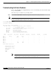
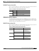
Table 10-1 describes the LEDs used to confirm and troubleshoot the operation of interface modules. The
LEDs on interface modules indicate the status of the modules and their ports.
100BASE-FX Interface Modules
The 100BASE-FX Ethernet interface module supports 100-Mbps Layer 2 or Layer 3 multimode fiber
connections. This module supports full-duplex connections and Fast EtherChannel operation. It provides
16 multimode fiber ports that have MT-RJ connectors. The 100BASE-FX interface module is available
with 16K or 64K of memory. Routing tables use this memory.
100BASE-FX Interface Module LEDs
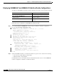
Table 10-2 describes the LEDs used to confirm and troubleshoot the operation of interface modules. The
LEDs on interface modules indicate the status of the modules and their ports.
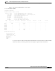
Table 10-1 10/100BASE-T Interface Module LED Descriptions
LED State Description
Lk Green Port is operational (a signal is detected).
Off No signal is detected.
Sp Green Port is operating at 100 Mbps.
Off Port is operating at 10 Mbps.
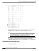
Table 10-2 100BASE-FX Interface Module LED Descriptions
LED State Description
Tx (Transmit) Green Port is transmitting a
packet. Green for
approximately 50 ms.
Off No signal is detected.
Rx (Receive) Green Port is receiving a packet.
Green for approximately
50 ms.
Off No signal is detected.
Link Green Port is operational (a
signal is detected).
Off No signal is detected.