
Troubleshooting guide


9-8
ATM and Layer 3 Switch Router Troubleshooting Guide
OL-1969-01
Chapter 9 Troubleshooting CES Connections and Network Clocking
Troubleshooting Network Clocking
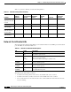
Table 9-1 provides a summary of network clocking features.
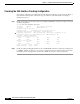
Network Clock Module LEDs
The network clock module faceplate LEDs provide status information for the BITS ports and the alarm
port. The LEDs are described in Table 9-2.
The following are major alarm conditions:
• A switchover from the primary clock source to the default clock source occurred.
• A switchover from the secondary clock source to the default clock source occurred.
• A loss of all references to the network clock source occurred while the network clock source was
set to free running.
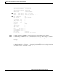
Table 9-1 Network Clocking Feature Summary
Platform
Up/Down
Detection
Loss of
Synchronization
Detection
Phase
Adjustment
Cutover
Stratum 3
Clock BITS
1
Port
1. BITS = Building Integrated Timing Supply
Clock Source
Preference
Catalyst 8540 MSR
with network clock
module
YesYes YesYesYesBest
Catalyst 8510 MSR Yes Yes Yes No No Medium
LightStream 1010
with FC-PFQ
Yes Yes Yes No No Medium
Catalyst 8540 MSR
without network
clock module
YesNo NoNoNoPoor
LightStream 1010
with FC-PCQ
YesNo NoNoNoPoor
Table 9-2 Network Clock Module LED Descriptions
LED Status Description
POWER Green
Off
The switch is powered on and the processor is functioning.
The switch is powered off.
STATUS Green
Red
Orange
The clock module is the primary network clock source.
The processor has crashed.
The clock module is operating in standby mode.
MAJOR
ALARM
Red
Off
A major alarm condition has occurred.
No major alarm reported.
MINOR
ALARM
Red
Off
A minor alarm condition has occurred.
No minor alarm reported.
CRITICAL
ALARM
Red
Off
Not supported.
No critical alarm reported.