
Troubleshooting guide

9-4
ATM and Layer 3 Switch Router Troubleshooting Guide
OL-1969-01
Chapter 9 Troubleshooting CES Connections and Network Clocking
CES Example Network
CES Example Network
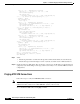
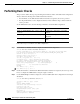
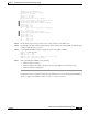
In the example network in Figure 9-1, the ATM switch routers in the administration building and the
remote sales building are each connected to a PBX and the WAN:
• AdminFl1Ls1—ATM switch router with CES interface located in the administration building
• SalesFl1Ls1—ATM switch router with CES interface located in the remote sales building
Figure 9-1 CES Example Network
This network example is used to describe the CES troubleshooting examples in the rest of this chapter.
For detailed configuration information about CES, refer to the “Configuring Circuit Emulation Services”
chapter in the ATM Switch Router Software Configuration Guide.
Initial Troubleshooting of CES
This section describes initial troubleshooting steps that you should perform when beginning to
troubleshoot a CES connection.
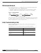
At the ATM switch router, use the following commands to check the CES configuration:
PBX1
AdminFI1Ls1 SalesFI1Ls1
PBX2
CBR 3/1/0
VPI 10, VCI 100
CBR 0/0/1
VPI 10, VCI 150
T1 T1
43262
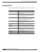
Command Purpose
show ces status Confirms the status of the CES circuits.
show ces circuit Confirms the configuration of the CES
PVCs.
show ces circuit interface cbr card/subcard/port
circuit-id
Confirms the configuration on the CES
interface.
show interfaces cbr card/subcard/port Confirms the status of the CES interface.