
Troubleshooting guide

9-3
ATM and Layer 3 Switch Router Troubleshooting Guide
OL-1969-01
Chapter 9 Troubleshooting CES Connections and Network Clocking
Performing Basic Checks
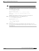
OAM-states: Not-applicable
Threshold Group: 1, Cells queued: 0
Rx cells: 0, Tx cells: 0
Tx Clp0:0, Tx Clp1: 0
Rx Clp0:0, Rx Clp1: 0
Rx Upc Violations:0, Rx cell drops:0
Rx Clp0 q full drops:0, Rx Clp1 qthresh drops:0
Rx connection-traffic-table-index: 10
Rx service-category: CBR (Constant Bit Rate)
Rx pcr-clp01: 4000
Rx scr-clp01: none
Rx mcr-clp01: none
Rx cdvt: 1024 (from default for interface)
Rx mbs: none
Tx connection-traffic-table-index: 10
Tx service-category: CBR (Constant Bit Rate)
Tx pcr-clp01: 4000
Tx scr-clp01: none
Tx mcr-clp01: none
Tx cdvt: none
Tx mbs: none
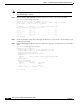
Step 4 Check the Rx service-category and Tx service-category fields for the CBR service.
Step 5 Check the Rx pcr-clp01 and Tx pcr-clp01 fields to ensure that the peak cell rate (PCR) is within the range
contracted with the service provider.
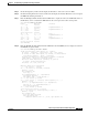
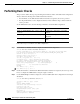
Step 6 Use the show dcu leds command to display the status of the CES port LEDs:
NewLs1010# show dcu leds
CBR3/1/0 [20]: idle
CBR3/1/1 [21]: idle
CBR3/1/2 [22]: Red (loss of signal and loss of cells)
CBR3/1/3 [23]: Red (loss of cells)
Step 7 If the port LED status is RED, do the following:
• Check the cable for damage.
• Check the length of the cable. It should not be more than 1000 feet or 304.8 meters long.
• Check the interface configuration.
For detailed interface configuration information about CES, refer to the “Configuring Circuit Emulation
Services” chapter in the ATM Switch Router Software Configuration Guide.