
Troubleshooting guide


8-35
ATM and Layer 3 Switch Router Troubleshooting Guide
OL-1969-01
Chapter 8 Troubleshooting Tag and MPLS Switching Connections
Troubleshooting MPLS ATM Connections
In Figure 8-6, all of the routers and ATM switch routers have loopback 0 interfaces configured with an
IP address. Each LSR uses these interfaces as the LDP router ID and LSR LDP ID. The display
representation for an LDP ID uses the following form:
[LDP router ID] : [Local label space ID]
The LDP ID “102.0.0.0/32” is an example of an “8540-ATM-PE1” loopback 0 interface. In this example,
2.0.0.1/8 is the IP address of the “8540-ATM-PE1” interface to “8540-ATM-P”, the provider switch
router.
The ATM MPLS interfaces are configured from the PE (provider edge) ATM switch router
(8540-ATM-PE1) through the provider core ATM switch router (8540-ATM-P) to the PE (provider edge)
ATM switch router (8540-ATM-PE2). The CE (customer edge) routers use these connections to
communicate between IP networks 11.1.0.0 and 14.0.0.0.
The MPLS example network shown in Figure 8-6 is used in the following examples of troubleshooting
MPLS VPN ATM network connections.
Verifying ATM Interface VRF Configurations
This section describes troubleshooting and verifying the VRF (VPN routing and forwarding instance)
over ATM interfaces on a ATM switch router.
To troubleshoot the VRF configuration, use the following commands:
Follow these steps to verify the VRF on MPLS VPN ATM interface connections:
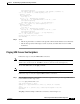
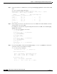
Step 1 Enter the show mpls interfaces command to verify the MPLS ATM interfaces on the ATM switch
routers, and enter the applicable show ip vrf commands to verify their associated route-indicators and
interface(s).
8540-ATM-PE1# show mpls interfaces
Interface IP Tunnel Operational
ATM1/0/0 Yes (tdp) No Yes (ATM labels)
Step 2 Verify that the neighbor attached to the MPLS interface is configured as (tdp) and the Operational field
indicates Yes. If it does not, check the interface MPLS configuration.
Step 3 Verify the Interface field matches the configuration of the target interface.
Step 4 Verify the VRF names routing attributes.
Step 5 Verify the Protocol field is up.
Command Purpose
show mpls interfaces Shows the MPLS forwarding
information.
show mpls ldp discovery Shows the status of the LDP discovery
process.
show ip vrf [detail] Shows the set of defined VRFs and
associated interfaces.
show ip route vrf [vrf-name] [protocol] Shows the IP routing table associated
with a VRF.