
Troubleshooting guide

8-27
ATM and Layer 3 Switch Router Troubleshooting Guide
OL-1969-01
Chapter 8 Troubleshooting Tag and MPLS Switching Connections
Troubleshooting MPLS VPN
Troubleshooting MPLS VPN Fast Ethernet Example
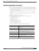
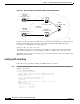
Figure 8-5 shows a customer VPN connection over a Fast Ethernet MPLS backbone connection, and is
used in the following examples of troubleshooting MPLS VPN network connections.
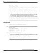
To troubleshoot an MPLS Ethernet configuration, use the following commands:
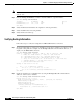
Verifying VRF Configurations
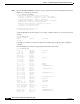
Follow these steps to verify the VRF on MPLS VPN interface connections:
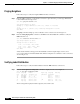
Step 1 Verify the VRFs are present on the ATM switch routers, and on their associated route-indicators and
interface(s), by entering the show ip vrf commands.
8540-PE2# show ip vrf
Name Default RD Interfaces
Green 200:1 FastEthernet2/0/1.2
Red 100:1 FastEthernet2/0/1.1
8540-PE2#
Step 2 Verify existence of the VRFs and their names are valid.
Step 3 Verify that each Default RD (route-indicator) field is the same at each provider edge ATM switch router.
If it is not, check the configuration of the interfaces.
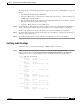
Step 4 Enter the show ip vrf detail command to check the VRFs more closely.
8540-PE2# show ip vrf detail Red
VRF Red; default RD 100:1
Interfaces:
FastEthernet2/0/1.1
Connected addresses are not in global routing table
Export VPN route-target communities
RT:100:1
Import VPN route-target communities
RT:100:1
No import route-map
No export route-map
8540-PE2#
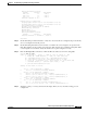
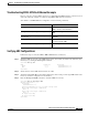
Command Purpose
show ip vrf detail [vrf-name] [interfaces] Shows detailed information on the
VRF(s) and associated interfaces.
show ip route vrf [detail] [vrf-name] [interfaces] Shows IP routing table associated with a
VRF.
show ip bgp vpnv4 vrf [all] [vrf-name]
[interfaces]
Shows VPN address information from the
BGP table.
show ip [protocol] database vrf [vrf-name] Show the protocol database information
associated with the VRF.
traceroute vrf [vrf-name] [interfaces] Shows data path between two MPLS
nodes.