
Troubleshooting guide

8-20
ATM and Layer 3 Switch Router Troubleshooting Guide
OL-1969-01
Chapter 8 Troubleshooting Tag and MPLS Switching Connections
Troubleshooting MPLS Connections
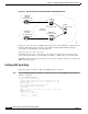
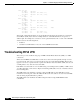
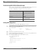
Figure 8-5 ATM Switch Router Fast Ethernet MPLS VPN Example Network
In Figure 8-5, all of the routers and ATM switch routers have loopback 0 interfaces configured with an
IP address. Each LSR uses these interfaces as the LDP router ID and LSR LDP ID. The display
representation for an LDP ID uses the following form:
[LDP router ID] : [Local label space ID]
The LDP ID “222.2.1.1/32” is an example of a “ProvEdge1” loopback 0 interface. In this example,
111.0.1.1/30 is the IP address of the “ProvEdge1” interface to “8540-P” the provider switch router.
The MPLS example network shown in Figure 8-5 is used in the following examples of troubleshooting
MPLS network connections.
Verifying CEF Switching
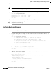
Follow these steps to troubleshoot CEF on the MPLS interface connections:
Step 1 Enter the show ip protocols command to confirm the protocol routes and MPLS networks, and all
neighbors, are present.
8540-PE1# show ip protocols
Routing Protocol is "ospf 222"
Outgoing update filter list for all interfaces is not set
Incoming update filter list for all interfaces is not set
Router ID 222.2.1.1
It is an autonomous system boundary router
Redistributing External Routes from,
connected
Number of areas in this router is 1. 1 normal 0 stub 0 nssa
Maximum path: 4
Routing for Networks:
111.0.1.0 0.0.0.255 area 0
111.0.2.0 0.0.0.255 area 0
222.2.1.1 0.0.0.0 area 0
68579
VPN Red
.18
.117
.118
.1.101
.102
8540-PE1
lo0 - 222.2.1.1/32
75k-CE1
lo0 - 222.2.2.1/32
VPN Red
75k-CE2
lo0 - 222.2.5.1/32
8540-PE2
lo0 - 222.2.1.2/32
8540-P
lo0 - 222.2.1.3/32
.2
.17
Network
111.0.1.0/30