
Troubleshooting guide

8-18
ATM and Layer 3 Switch Router Troubleshooting Guide
OL-1969-01
Chapter 8 Troubleshooting Tag and MPLS Switching Connections
MPLS Overview
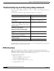
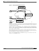
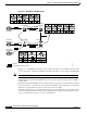
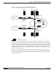
Figure 8-4 ATM MPLS Example Network Packet Transmission
The packet from network 130.0.0.0 enters router AdminRt1 at Ethernet interface 2/3 with a destination
IP address on network 180.0.0.0. The router performs a standard routing table lookup and determines
the packet should be routed out ATM interface 0/0 to the next hop interface 140.0.0.1 on interface ATM
1/0/0. By using CEF (Cisco Express Forwarding) the Layer 3 switched packet interface FIB (Forwarding
Information Base) is queried and the next hop is determined to be reached through ATM MPLS interface
3/0/0. Prior to transmission to the next LSR, an MPLS label (or VPI/VCI) is appended to the packet just
before the destination IP address.
From this point on, through the MPLS network, the only information that is checked by the successive
LSRs is the label information in the packet. When the packet reaches the edge LSR, the MPLS label is
“popped off” (deleted) the stack and subsequent switching is completed using Layer 3 protocols and
standard routing practices.
130.0.0.0
140.0.0.0
150.0.0.0
160.0.0.0
170.0.0.0
180.0.0.0
e2/3 a0/0
e0/3 a1/0
a1/1/0
a1/2/0
a3/0/0
a3/0/0
a1/0/0
a9/0/0
.1
.1
.1
.1
.2
.2
.2
.2.1 .1
68271
SalesRT1
Loopback 5.5.5.5
Routing
table
AdminLSR1
Loopback 2.2.2.2
SalesSR3
Loopback 4.4.4.4
NetLSR2
Loopback 3.3.3.3
AdminRt1
Loopback 1.1.1.1
FIB
table
LFIB
table
Routing
table
FIB
table
LFIB
table
= Packet
= Packet with VPI/VCI label