
Troubleshooting guide

8-16
ATM and Layer 3 Switch Router Troubleshooting Guide
OL-1969-01
Chapter 8 Troubleshooting Tag and MPLS Switching Connections
MPLS Overview
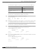
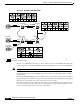
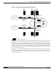
Figure 8-3 ATM MPLS LFIB Table Update
In Figure 8-3, AdminLSR1 is the ingress point for packets from the router AdminRt1. When the LSR
receives the packet, it determines the FEC and determines the LSP to use by looking in the LFIB table.
Note The LFIB table is propagated using the LDP discover mechanism shown in Figure 8-2.
AdminLSR1 then adds the label (VPI/VCI) 65,180 to the packet, and forwards the packet out ATM
interface 0/1/0.
The intermediate LSR (NetLSR2) takes the labeled packet, and pairs the incoming interface and label,
using a lookup table to determine the outgoing interface and label. After swapping the incoming label
with the new outgoing label, the packet is forwarded out to the next LSR.
The label swapping process is continued at each LSR, up to the last LSR. The egress LSR performs the
same look up as the intermediate LSRs, but the outgoing label is stripped off and the packet is either
routed, or switched using a Layer 3 protocol to its destination.
a0/0 a0/0/0
a0/1/0
e1/0
a2/0/0
a1/1/0
a1/0/0
a2/1/0
a3/0/0
e3/1/0
e3/2/0
68273
AdminLSR1
NetLSR2
NetLSR3
SalesRt1
172.68.10/24
SalesLSR4
e2/0
SalesRt2
172.68.44/24
AdminRt1
= Packet
= Packet with VPI/VCI label