
Troubleshooting guide

8-6
ATM and Layer 3 Switch Router Troubleshooting Guide
OL-1969-01
Chapter 8 Troubleshooting Tag and MPLS Switching Connections
Initial Troubleshooting of Tag Switching
State: Oper; PIEs sent/rcvd: 2120/2119; Downstream on demand
Up time: 02:31:38
TDP discovery sources:
ATM0/1/0.18
Step 2 Check the Peer TDP Ident field. This field indicates the TDP identifier of the neighbor (peer device) for
this session.
Step 3 Check the Local TDP Ident field. This field indicates the TDP identifier for the local tag switching
switch router or router for this session.
Step 4 Check the TCP connection field. This field indicates the TCP connection used to support the TDP
session. The format for displaying the TCP connection is peer IP address.peer port local IP
address.local port.
Step 5 Check the PIEs sent/rcvd (Protocol Information Element sent or received) field. This field indicates the
number of TDP PIEs sent to and received from the session peer device. The count includes the
transmission and receipt of periodic keepalive PIEs, which are required for maintenance of the TDP
session.
Step 6 Check the Up time field. This field indicates the length of time the TDP session has existed.
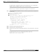
Follow these steps to confirm the tag switching interface configuration on the switch router:
Step 1 Enter the show tag-switching interfaces command to confirm the configuration and connection of the
tag switching interfaces.
AdminFl1Ls1# show tag-switching interfaces
Interface IP Tunnel Operational
ATM1/0/0 Yes No Yes
ATM3/0/0 Yes No Yes
AdminFl1Ls1#
Step 2 Check the IP field. This field indicates whether the interface is configured to tag IP packets.
Step 3 Check the Operational field. This field shows whether the packets are being tagged.
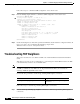
Step 4 Enter the show tag-switching interfaces detail command to confirm the tag switching VPI range on an
interface.
AdminFl1Ls1# show tag-switching interfaces detail
Interface ATM1/0/0:
IP tagging enabled
TSP Tunnel tagging not enabled
Tagging not operational
MTU = 4470
ATM tagging: Tag VPI = 1, Control VC = 0/32
Interface ATM3/0/0:
IP tagging enabled
TSP Tunnel tagging not enabled
Tagging not operational
MTU = 4470
ATM tagging: Tag VPI range = 5 - 6, Control VC = 6/32
<Additional text omitted.>
Step 5 Check the IP tagging enabled field. This field indicates whether tag switching is enabled on this
interface.
Step 6 Check the ATM tagging field. This field indicates the VPI range of the interface.