
Troubleshooting guide

6-65
ATM and Layer 3 Switch Router Troubleshooting Guide
OL-1969-01
Chapter 6 Troubleshooting Switch Router ATM Network Connections
Using PNNI Trace Connection
For additional information about PNNI trace connection initiation, refer to the “Configuring ATM
Routing and PNNI” chapter in the ATM Switch Router Software Configuration Guide.
Initiating a Trace Connection
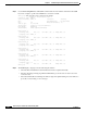
To initiate a trace Connection on a PNNI interface connection, use one of the following command in
EXEC configuration mode:
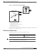
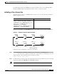
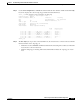
Figure 6-7 is an example of an ATM PNNI network used to display the trace connection initialization.
Figure 6-7 PNNI Trace Connection Network Example
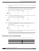
Follow these steps to initiate trace connection on an interface:
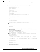
Step 1 Use the atm pnni trace connection command to trace a connection on an ATM interface.
Switch_10# atm pnni trace connection interface atm 1/0/2 direction incoming vpi 0 vci 136
endpt-reference 6 call-reference-trace connection-id-trace
Request accepted - request index:20
Step 2 Confirm the trace connection request is accepted. If accepted, a message similar to the previous example
appears after entering the atm pnni trace connection command.
Note You can use the request index number displayed in the confirmation message to display the specific
connection trace for this interface.
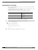
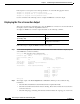
Command Purpose
atm pnni trace connection interface interface
{dlci dlci | direction {incoming | outgoing}
{call-reference value [endpt-reference value] |
{vpi vpi [vci vci]} [endpt-reference value]}
[age-timeout {seconds | none}]
[call-reference-trace] [connection-id-trace]
[fail-timeout seconds] [no-pass-along]
Configures ATM PNNI connection-trace.
Connection trace
started at ATM 1/0/2
Router_1
68147
Router_2
Switch_10
Switch_9Switch_8
Switch_5
Switch_3
Switch_6