
Troubleshooting guide

6-55
ATM and Layer 3 Switch Router Troubleshooting Guide
OL-1969-01
Chapter 6 Troubleshooting Switch Router ATM Network Connections
Troubleshooting Virtual Path Tunnel Connections
Step 7 Use the show atm pnni local-node command to check the node IDs and peer group IDs of higher-level
local nodes. If they are not based on the prefix of the ATM address, verify that no other peer group IDs
have been manually configured. Also, verify that the lowest-level node on the switch router has been
disabled and reenabled since the last time the active switch router ATM address was reconfigured.
Step 8 If an unexpected summary address appears in the list, use the show running-config command to make
sure that the summary address has not been manually configured.
If a summary prefix has been configured, but it is not possible to route to the summarized addresses from
another peer group, check for an overlapping summary address within the other peer group. If the
overlapping summary is for an automatically generated prefix, it could mean the ATM node addresses
need to be modified to give unique prefixes for the ancestors of the two peer groups.
Troubleshooting Virtual Path Tunnel Connections
This section describes how to troubleshoot virtual path (VP) tunnels. VP tunnels are used primarily
between private ATM networks across public ATM networks, such as telecom carriers, that do not yet
support ATM signalling. Signaling traffic is mapped into the VP tunnel and the switch routers that
allocate virtual channel connections (VCCs) on that VP instead of the default VP=0. With these
connections, signaling can travel transparently through the public network.
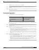
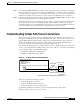
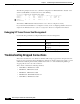
In the example network in Figure 6-5, the PVC tunnel connection configured between the switch router
on Floor 1 of the administration building and the switch router on Floor 1 of the remote sales building
has the following interface and subinterface numbers:
• AdminFl1ls1, ATM interface 1/0/0, PVP 99
• RsalFl1Ls1, ATM interface 4/0/0, PVP 99
Figure 6-5 VP Tunnel Test in the Example Network
This section contains the following procedures:
• Checking VP Tunnel Configuration
• Checking Virtual Path PVP Configuration
• Debugging VP Tunnel Connection Management
For detailed configuration information, see the “Configuring Interfaces” chapter in the
ATM Switch Router Software Configuration Guide.
Administration building
Remote sales
building
PVP
12118
(AdminFI1Ls1)
PVP IF = 1/0/0.99
ATM addr =
33.3333.3333.3333.3333.3333.3333.3333.3333.00
(RsalFl1Ls1)
PVP IF = 4/0/0.99
ATM addr =
44.4444.4444.4444.4444.4444.4444.4444.4444.00
Public ATM
network