
Troubleshooting guide

6-29
ATM and Layer 3 Switch Router Troubleshooting Guide
OL-1969-01
Chapter 6 Troubleshooting Switch Router ATM Network Connections
Troubleshooting SVC Connections on a PNNI Routing Network
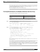
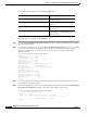
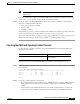
Step 4 Turn off further debug printouts using the no debug all command.
EngFl1Ls1# debug atm sig-events atm 0/0/0
<Information Deleted>
PNNI: SOURCE ROUTE
DTL 1> 2 Nodes
DTL 1> 56:160:47.00918110000000613E7B2F01.00613E7B2F99.00 ATM0/1/1
DTL 1> 56:160:47.009181100000006122222222.006122222222.00 ATM0/3/1
DTL 2> 2 Nodes
DTL 2> 24:40:47.009181100000000000000000.0060705BAD01.00 4276000
24:160:47.009181000000060705BD900.0060705BD900.00 0
<Information Deleted>
EngFl1Ls1# no debug all
Step 5 Examine the initial SOURCE ROUTE. The last node ID listed for the lowest-level DTL (shown as
DTL 1>) is the exit border node for the local peer group. Make a note of the exit border node ID and port.
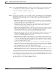
Follow these steps to determine the internal node number and name corresponding to the exit border
node ID for the terminating end switch router on the UNI interface (EngFl1Ls1 ATM 0/0/0 in this
example):
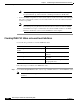
Step 1 Use the show atm pnni identifiers command to determine the internal node number and name
corresponding to the exit border node ID.
The lowest-level neighbor node on the other end of the exit border port is the entry border node for the
next peer group.
Note The show atm pnni topology node exit-border-node-number command shows the neighbor
node name of the entry border node if the interface is up.
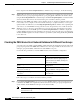
Step 2 After determining the next entry border node, repeat the troubleshooting steps in the following sections
on that node:
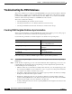
• Debugging SVC Signalling, page 6-21
• Debugging PNNI SVC Routing, page 6-24
• Checking ATM Routes, page 6-25
• Checking PNNI Topology, page 6-26
• Checking SVC Downstream, page 6-27
Step 3 Repeat these steps on that node and continue until either the terminating peer group is reached or the
problem is isolated.