
Troubleshooting guide

6-25
ATM and Layer 3 Switch Router Troubleshooting Guide
OL-1969-01
Chapter 6 Troubleshooting Switch Router ATM Network Connections
Troubleshooting SVC Connections on a PNNI Routing Network
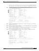
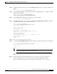
Step 6 If the initial Source Route Reply code is PNNI_SUCCESS and there are further tries with Crankback
Set, the problem is downstream of this switch router. Note the original SOURCE ROUTE, shown as a
list of DTLs (which are lists of node IDs and ports), as well as any calculated port list to the next node.
Continue with the “Checking SVC Downstream” section on page 6-27.
If the Source Route Reply code is other than PNNI_SUCCESS, the actual code gives information about
the nature of the problem when routing constraints are not met.
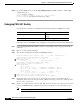
Checking ATM Routes
Use the following command to list the routes and destination prefixes:
Follow these steps to list the routes learned by the originating end of the switch router on the UNI
interface:
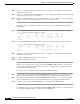
Step 1 Use the show atm route command to display a list of routes learned by the originating end switch router
UNI interface on RemDvLs1 ATM 3/1/1 as shown in Figure 5-3.
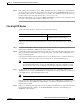
Step 2 Confirm that a prefix matching the intended target address is shown with a ST (State) UP. If there is more
than one prefix that exactly matches the corresponding prefix of the target address, PNNI will choose
the longest matching prefix.
If the longest matching prefix ST is DN (Down) for a node other than node 1, it indicates that there is
no connectivity to that node. Continue to the following section “Checking PNNI Topology.”
Note If the State is DN for a desired prefix on node 1 (this node), then check for proper status for
the terminating UNI interface on this node. The ILMI Auto-Cfg (auto configuration) status
must be shown as done, or auto configuration must be turned off for the prefix state to be UP.
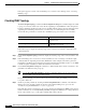
Step 3 Confirm that the Node n shown for the longest matching prefix is the terminating switch router
(EngFl1Ls1 for this example). If PNNI Hierarchy is being used, the node can instead be a logical group
node (LGN) ancestor of the terminating switch router.
Note Use the show atm pnni identifiers command to determine which node n represents.
If the wrong node is listed with a matching prefix, check for proper ATM address configuration for the
destination switch router (EngFl1Ls1 in this example), as well as for its UNI interface and for any
hierarchy ancestor LGN.
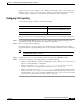
Step 4 If there is no matching prefix appearing in the list of prefixes reachable from the originating end switch
router (RemDvLs1 in this example), use the show atm route command on the terminating node
(EngFl1Ls1 in this example).
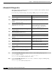
Command Purpose
show atm route Displays the destination prefixes the
originating switch router has learned.