
Troubleshooting guide

6-6
ATM and Layer 3 Switch Router Troubleshooting Guide
OL-1969-01
Chapter 6 Troubleshooting Switch Router ATM Network Connections
Troubleshooting PVP and PVC Connections
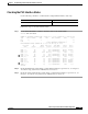
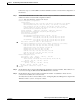
Step 3 Use the show atm ilmi-status atm command to confirm VPI and VCI ranges of the PVC connection at
the manufacturing building.
ManuFl1Ls1# show atm ilmi-status atm 0/1/0
Interface : ATM0/1/0 Interface Type : Private NNI
ILMI VCC : (75, 150) ILMI Keepalive : Disabled
ILMI State: UpAndNormal
Peer IP Addr: 172.20.41.93 Peer IF Name: ATM0/1/0
Peer MaxVPIbits: 8 Peer MaxVCIbits: 14
Peer MaxVPCs: 255 Peer MaxVCCs: 16383
Peer MaxSvccVpi: 255 Peer MinSvccVci: 33
Peer MaxSvpcVpi: 255
Configured Prefix(s) :
47.0091.8100.0000.0040.0b0a.2a81
ManuFl1Ls1#
Step 4 Check the Peer MaxVPCs and Peer MaxVCCs fields. They indicate the VPI and VCI ranges of the PVC
connection at the administration building.
Step 5 If either the VPI or VCI of the PVC are configured incorrectly, see Chapter 6, “Configuring Virtual
Connections,” of the ATM Switch Router Software Configuration Guide.
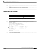
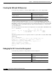
Checking the UBR Resources
Use the following commands to confirm unspecified bit rate (UBR) for the PVP and PVC best-effort
connection limit configuration:
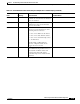
Command Purpose
show atm interface resource atm
card/subcard/port
For UBR connections, confirms
connection admission control (CAC)
best-effort limit configuration.
show atm resource For VBR and CBR connections, confirms
that the resources requested are available.