
Troubleshooting guide

6-2
ATM and Layer 3 Switch Router Troubleshooting Guide
OL-1969-01
Chapter 6 Troubleshooting Switch Router ATM Network Connections
Troubleshooting PVP and PVC Connections
• Proper interface types on both ends of the cable.
Troubleshooting PVP and PVC Connections
This section describes how to troubleshoot permanent virtual paths (PVPs) and permanent virtual
channels (PVCs). PVP and PVC connections are used primarily between buildings as the backbone
connection and between frequently accessed hosts, such as the Domain Name System (DNS) server.
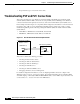
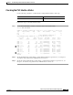
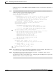
In the example network in Figure 6-1, the primary PVC configured as the backbone connection between
the switch router on Floor 1 in the administration building and the switch router on Floor 1 in the
manufacturing building has the following virtual path identifier (VPI) and virtual channel identifier
(VCI) numbers:
• AdminFl1Ls1, ATM interface 3/1/0, VPI 50, and VCI 100
• ManuFl1Ls1, ATM interface 0/1/0, VPI 75, and VCI 150
Figure 6-1 PVC VPI and VCI Test in the Example Network
This section contains the following procedures:
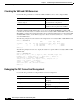
• Checking the PVC Interface Status
• Checking the VPI and VCI Numbers
• Checking the VPI and VCI Ranges
• Checking the UBR Resources
• Checking the VBR and CBR Resources
• Debugging the PVC Connection Management
For detailed configuration information, see the “Configuring Virtual Connections” chapter in the
ATM Switch Router Software Configuration Guide. For detailed information about configuring PVCs
and traffic shaping on the Catalyst 5000 and 6000 ATM modules, see the ATM Configuration Guide and
Command Reference: Catalyst 5000 and 6000 ATM Modules.
Manufacturing building
Administration building
E-mail and meeting
database servers
(AdminFl1Ls1)
(ManuFl1Ls1)
3/1/0
PNNI
0/1/0
12092
VPI 75, VCI 150VPI 50, VCI 100