
Troubleshooting guide

5-58
ATM and Layer 3 Switch Router Troubleshooting Guide
OL-1969-02
Chapter 5 Troubleshooting Switch Router ATM Interface Connections
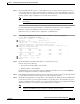
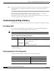
Troubleshooting Channelized DS3 and E1 Frame Relay Interfaces
No alarms
detected.
Up None None
Any alarms
detected by the
controller are
displayed here.
The possible
alarms are:
• Transmitter is sending remote alarm.
• Transmitter is sending alarm
indication signal (AIS).
• Receiver has loss of signal.
• Receiver is getting AIS.
• Receiver has loss of frame.
• Receiver has remote alarm.
• Receiver has no alarms.
See Table 5-1 for description of these
errors.
Framing is Shows the current
framing type.
It should match the framing mode
configuration of the destination port.
Check the framing mode configuration on
the destination port.
Line Code is It should match the line code
configuration of the destination port.
Check the framing mode configuration on
the destination port.
Data in current
interval (251
seconds elapsed)
Shows the current accumulation period, which rolls into a 24 hour accumulation every 15 minutes. The
accumulation period is from one to 900 seconds. The oldest 15-minute period falls off the back of the
24-hour accumulation buffer.
Line Code
Violations
Indicate the
number of
bipolar violation
(BPV) or
excessive zeros
(EXZ) errors.
The conditions
that cause this
error to
increment will
vary with the line
coding.
Bipolar violation:
AMI—Receiving two successive pulses
of the same polarity.
B3ZS or HDB3—Receiving two
successive pulses of the same polarity, but
these pulses are not part of zero
substitution.
Excessive zeros:
AMI—Receiving more than 15
contiguous zeros.
B3ZS—Receiving more than seven
contiguous zeros.
Path Code
Violations
Indicates a frame synchronization bit
error in the D4 and E1-no CRC formats,
or a CRC error in the Extended
Superframe (ESF) and E1-CRC formats.
Slip Secs Indicates the replication or deletion of the
payload bits of a domestic trunk interface
(DS1) frame. A slip might happen when
there is a difference between the timing of
a synchronous receiving terminal and the
received signal.
FR Loss Secs Indicates the number of seconds an Out of
Frame (OOF) error is detected.
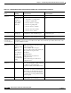
Table 5-14 Channelized DS3 and E1 Frame Relay Port Adapter show controller Display (continued)
Field
Indication
(Severity) Error and Cause Recommendation