
Troubleshooting guide

5-50
ATM and Layer 3 Switch Router Troubleshooting Guide
OL-1969-02
Chapter 5 Troubleshooting Switch Router ATM Interface Connections
Troubleshooting 25-Mbps Interfaces
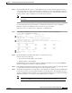
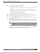
Step 5 Check the Input Counters and Output Counters fields. If the errors and the input and output difference
exceed 0.5 to 2.0 percent of traffic on the interface, the interface is experiencing congestion and
dropping cells.
If you determine that the physical interface is configured incorrectly, refer to the “Configuring
Interfaces” chapter in the ATM Switch Router Software Configuration Guide.
If the interface is still not operating correctly, continue with the troubleshooting process in Chapter 6,
“Troubleshooting Switch Router ATM Network Connections.”
Troubleshooting 25-Mbps Interfaces
This section describes specific processes and commands used to troubleshoot the 25-Mbps port adapter.
Port Adapter LEDs
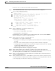
The port adapter faceplate LEDs provide status information for individual 25-Mbps UTP interface
connections of the port adapter. The LEDs are described in Table 5-12.
Note Use the show controllers command to remotely display the LED status.
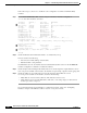
Displaying Interface Port Configuration
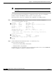
To display the 25-Mbps interface configuration, use the following commands:
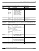
Table 5-12 25-Mbps UTP Port Adapter LED Descriptions
LED Status Description
TX (Transmit) Off
Flashing green
Flashing yellow
Steady yellow
Red
No receive line activity indication.
Cells are being received. LED blinks every 5 seconds and pulse rate
increases with data rate.
Loopback.
FERF alarm.
1
Alarm indication (LOF
2
, LCD
3
).
1. FERF = far-end receive failure
2. LOF = loss of frame
3. LCD = loss of cell delineation
Command Purpose
show interfaces atm card/subcard/port Shows the status of the physical interface.
show atm interface atm card/subcard/port Shows the interface configuration.
show controllers atm card/subcard/port Shows the interface memory management
and error counters.