
Troubleshooting guide

5-49
ATM and Layer 3 Switch Router Troubleshooting Guide
OL-1969-02
Chapter 5 Troubleshooting Switch Router ATM Interface Connections
Troubleshooting CES T1 and CES E1 Interfaces
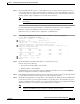
Step 7 Check the CRC field. The presence of many CRC errors but not many collisions indicates excessive
noise. If the number is too high, check the cables for damage. If you are using UTP cables, make sure
you are using category 5 cables and not another type, such as category 3. Also check the clock mode,
framing, and line coding configuration for each end of the connection.
Note Errors and the input and output difference should not exceed 0.5 to 2.0 percent of traffic on
the interface.
If you determine that the physical interface is configured incorrectly, refer to the “Configuring
Interfaces” chapter in the ATM Switch Router Software Configuration Guide.
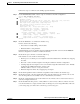
Follow these steps to troubleshoot the configuration of a CES interface:
Step 1 Use the show ces interface cbr card/subcard/port command to check the configuration.
Switch# show ces interface cbr 3/0/0
Interface: CBR3/0/0 Port-type:T1-DCU
IF Status: UP Admin Status: UP
Channels in use on this port:
LineType: ESF LineCoding: B8ZS LoopConfig: NoLoop
SignalMode: NoSignalling XmtClockSrc: network-derived
DataFormat: UnStructured AAL1 Clocking Mode: Synchronous LineLength: 0_110
LineState: XmtAIS LossOfSignal
Errors in the Current Interval:
PCVs 0 LCVs 0 ESs 0 SESs 0 SEFSs 0
UASs 0 CSSs 0 LESs 0 BESs 0 DMs 0
Errors in the last 24Hrs:
PCVs 0 LCVs 0 ESs 0 SESs 0 SEFSs 0
UASs 0 CSSs 0 LESs 0 BESs 0 DMs 0
Input Counters: 0 cells, 0 bytes
Output Counters: 0 cells, 0 bytes
Switch#
Step 2 Check the IF Status and Admin Status fields to see whether they are up.
If down, check for the following:
• Disconnected or faulty cabling—Check cables.
• Hardware failure—Swap hardware.
If administratively down, the interface has been administratively taken down. Use the no shutdown
interface configuration command to reenable the interface.
Step 3 If the DataFormat field indicates that the circuit is unstructured, check the AAL1 Clocking Mode field
to ensure that it matches the AAL1 clocking mode of the destination interface.
Step 4 Check the LineLength field to see if the value is correct. Measure the distance between the ATM switch
router and the customer provided equipment (CPE) or regenerating device. The maximum supported
distance for CES T1 interfaces is 650 feet, or 198 meters. The maximum supported distance for CES E1
interfaces and 820 feet, or 248.5 meters. The default value is 0 to 110 feet.
Note For detailed cabling and hardware information, refer to the “CES T1 and E1 Port Adapters”
chapter in the ATM Port Adapter and Interface Module Installation Guide.