
Troubleshooting guide

5-39
ATM and Layer 3 Switch Router Troubleshooting Guide
OL-1969-02
Chapter 5 Troubleshooting Switch Router ATM Interface Connections
Troubleshooting DS3 and E3 Interfaces
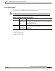
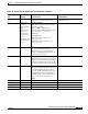
Port Adapter LEDs
The port adapter faceplate LEDs provide status information for individual DS3 and E3 coaxial interface
connections of the port adapter. The LEDs are described in Table 5-9.
Note Use the show controllers command to remotely display the LED status.
Table 5-9 DS3 and E3 Port Adapter LED Description
LED Status Description
RX (Receive) Off
Flashing green
Red
LOS
1
or port adapter is shut down.
Cells are being received. LED blinks every 5 seconds and pulse rate
increases with data rate.
Alarm (LOF
2
, LCD
3
, AIS
4
).
1. LOS = loss of signal
2. LOF = loss of frame
3. LCD = loss of cell delineation
4. AIS = alarm indication signal
TX (Transmit) Off
Flashing green
Flashing yellow
Steady yellow
No transmit line activity indication.
Cells are being transmitted. LED pulse rate increases with data rate.
Loopback.
FERF alarm.
5
5. FERF = far-end receive failure