
Troubleshooting guide

5-38
ATM and Layer 3 Switch Router Troubleshooting Guide
OL-1969-02
Chapter 5 Troubleshooting Switch Router ATM Interface Connections
Troubleshooting DS3 and E3 Interfaces
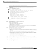
Table 5-1 describes the Port status and Active defect errors the might appear, the cause of the error, and
a recommended solution.
If you determine that the physical interface is configured incorrectly, refer to the “Configuring
Interfaces” chapter in the ATM Switch Router Software Configuration Guide.
If the configuration of the interface is not the problem, use the information in OAM Loopback Testing,
page 5-9 to configure a hard loopback to test the interface.
Next, see the Using the debug Commands to Troubleshoot an Interface, page 5-19 to further troubleshoot
the interface.
If the interface is still not operating correctly, proceed with the troubleshooting process in Chapter 6,
“Troubleshooting Switch Router ATM Network Connections.”
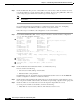
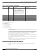
Troubleshooting DS3 and E3 Interfaces
This section describes specific processes and commands used to troubleshoot the DS3 and E3 port
adapters.
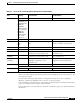
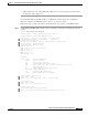
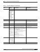
febe
4
The M-frame uses P bits to check the
line's parity. The M-subframe uses C bits
in a format called C-bit parity, which
copies the result of the P bits at the source
and checks the result at the destination.
An ATM interface reports detected C-bit
parity errors back to the source via a
FEBE.
b1
5
fe
6
plcp_febe
7
hcs
8
uicell
9
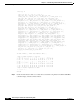
1. lcv = line code violation
2. ferr = framing bit error event counter
3. bee = CRC-6 in ESF, Framing bit error in SF
4. febe = far-end block error
5. b1= PLCP BIP errors
6. fe = PLCP framing pattern octet errors
7. plcp_febe = PLCP FEBE errors
8. hcs = uncorrectable HEC errors
9. uicell = unassigned/idle cells dropped
Tabl e 5-8 T1 and E1 Port Adapter show controller Display
Field
Indication
(Severity) Error and Cause Recommendation