
Troubleshooting guide

5-37
ATM and Layer 3 Switch Router Troubleshooting Guide
OL-1969-02
Chapter 5 Troubleshooting Switch Router ATM Interface Connections
Troubleshooting T1 and E1 Interfaces
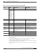
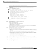
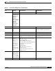
Tabl e 5-8 T1 and E1 Port Adapter show controller Display
Field
Indication
(Severity) Error and Cause Recommendation
Port status Good Signal None None
Errors could be:
SECTION LOS
SECTION LOF
LINE AIS
LINE RDI
PATH LOP (Path
Loss of Pointer)
PATH AIS
PATH RDI
Invalid OOCD
(out of cell
delineation)
See Table 5-1 for more information about these errors.
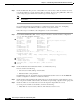
Loopback: None None None
Line
Diag
PIF
Loopback connections are for testing
only.
Use the no loopback command on the
interface to disable loopback testing.
TX Led: Traffic Pattern Any other indication is an alarm. See Table 5-7 for LED descriptions.
RX Led: Traffic Pattern Any other indication is an alarm. See Table 5-7 for LED descriptions.
T1/E1 Framing
mode:
sts-3c It should match the framing mode
configuration of the destination port.
Check the framing mode configuration on
the destination port.
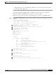
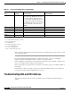
lcv
1
Indicate the
number of
bipolar violation
(BPV) or
excessive zeros
(EXZ) errors.
The conditions
that cause this
error to
increment will
vary with the line
coding.
Bipolar violation:
AMI—Receiving two successive pulses
of the same polarity.
B3ZS or HDB3—Receiving two
successive pulses of the same polarity, but
these pulses are not part of zero
substitution.
Excessive zeros:
AMI—Receiving more than 15
contiguous zeros.
B3ZS—Receiving more than seven
contiguous zeros.
ferr
2
Indicate the
number of times
that an incorrect
pattern for the
F1-to-F4 framing
bits was detected.
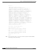
bee
3