
Troubleshooting guide

5-35
ATM and Layer 3 Switch Router Troubleshooting Guide
OL-1969-02
Chapter 5 Troubleshooting Switch Router ATM Interface Connections
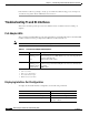
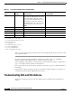
Troubleshooting T1 and E1 Interfaces
• Cable damage. If you are using UTP cables, make sure you are using category 5 cables and not
another type, such as category 3.
If you determine that the physical interface is configured incorrectly, refer to the “Configuring
Interfaces” chapter in the ATM Switch Router Software Configuration Guide.
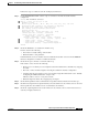
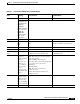
Follow these steps to display the memory management and error counters of a T1 ATM interface:
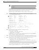
Step 1 Use the show controllers atm card/subcard/port command to check memory management and error
counters.
Switch# show controllers atm 4/1/0
IF Name: ATM4/1/0, SUNI PDH Chip Base Address: A8F08000
IF Name: ATM4/1/0, framer Base Address: A8F09000
Port type: T1 Port rate: 1500 Kbps Port medium: UTP
Port status:Good Signal Loopback:None Flags:8008
showdow clk reg value AA
TX Led: Traffic Pattern RX Led: Traffic Pattern CD Led: Green
TX clock source: network-derived
T1 Framing Mode: ESF PLCP format
FERF on AIS is on
FERF on LCD is on (n/a in PLCP mode)
FERF on RED is on
FERF on OOF is on
FERF on LOS is on
LBO: between 0-110
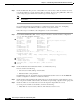
Counters:
Key: txcell - # cells transmitted
rxcell - # cells received
lcv - # line code violations
ferr - # framing bit error event counter
bee - # bit error event, CRC-6 in ESF, Framing bit error in SF
b1 - # PLCP BIP errors
fe - # PLCP framing pattern octet errors
plcp_febe- # PLCP FEBE errors
hcs - # uncorrectable HEC errors
uicell - # unassigned/idle cells dropped
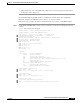
txcell:8028282, rxcell:8027930
lcv:3, ferr:0, bee:2
febe:0, b1:0, fe:0, plcp_febe:0, hcs:0, uicell:120525350
PDH errored secs:
lcv:1, ferr:0, bee:1
febe:0, b1:0, fe:0, plcp_febe:0, hcs:0
PDH error-free secs:
lcv:6479343, ferr:6479344, bee:6479343
febe:0, b1:6479344, fe:6479344, plcp_febe:6479344, hcs:6479344