
Troubleshooting guide

5-32
ATM and Layer 3 Switch Router Troubleshooting Guide
OL-1969-02
Chapter 5 Troubleshooting Switch Router ATM Interface Connections
Troubleshooting T1 and E1 Interfaces
If the interface is still not operating correctly, proceed with the troubleshooting process in Chapter 6,
“Troubleshooting Switch Router ATM Network Connections.”
Troubleshooting T1 and E1 Interfaces
This section describes specific processes and commands used to troubleshoot the T1 and E1 port
adapters.
Port Adapter LEDs
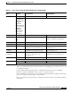
The port adapter faceplate LEDs provide status information for individual T1 and E1 coaxial and UTP
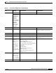
interface connections of the port adapter. The LEDs are described in Table 5-7.
Note Use the show controllers command to remotely display the LED status.
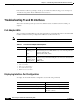
Displaying Interface Port Configuration
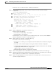
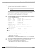
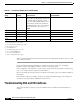
To display the T1 and E1 interface configuration, use the following commands:
Table 5-7 T1 and E1 Port Adapter LED Descriptions
LED Status Description
RX (Receive) Off
Flashing green
Red
LOS
1
or port adapter is shut down.
Cells are being received. LED blinks every 5 seconds and pulse rate
increases with data rate.
Alarm (LOF
2
, LCD
3
, AIS
4
).
1. LOS = loss of signal
2. LOF = loss of frame
3. LCD = loss of cell delineation
4. AIS = alarm indication signal
TX (Transmit) Off
Flashing green
Flashing yellow
Steady yellow
No transmit line activity indication.
Cells are being transmitted. LED pulse rate increases with data rate.
Loopback.
FERF
5
alarm.
5. FERF = far-end receive failure
Command Purpose
show interfaces atm card/subcard/port Shows the status of the physical interface.
show atm interface atm card/subcard/port Shows the interface configuration.
show controllers atm card/subcard/port Shows the interface memory management
and error counters.