
Troubleshooting guide

5-29
ATM and Layer 3 Switch Router Troubleshooting Guide
OL-1969-02
Chapter 5 Troubleshooting Switch Router ATM Interface Connections
Troubleshooting OC-3c, OC-12c, and OC-48c Interfaces
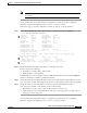
Note Errors and the input and output difference should not exceed 0.5 to 2.0 percent of traffic on
the interface.
If you determine that the physical interface is configured incorrectly, refer to the “Configuring
Interfaces” chapter in the ATM Switch Router Software Configuration Guide.
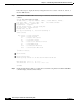
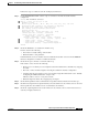
Follow these steps to show the configuration of an OC-3c, OC-12c, or OC-48c interface:
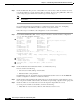
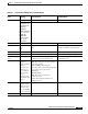
Step 1 Use the show atm interface atm card/subcard/port command to check the configuration.
Switch# show atm interface atm 1/0/0
Interface: ATM1/0/0 Port-type: oc3suni
IF Status: UP Admin Status: up
Auto-config: enabled AutoCfgState: completed
IF-Side: Network IF-type: UNI
Uni-type: Private Uni-version: V3.1
Max-VPI-bits: 2 Max-VCI-bits: 10
Max-VP: 255 Max-VC: 16383
ConfMaxSvpcVpi: 255 CurrMaxSvpcVpi: 3
ConfMaxSvccVpi: 255 CurrMaxSvccVpi: 3
ConfMinSvccVci: 33 CurrMinSvccVci: 33
Svc Upc Intent: pass Signalling: Enabled
ATM Address for Soft VC: 47.0091.8100.0000.0000.0000.0001.4000.0c80.8000.00
Configured virtual links:
PVCLs SoftVCLs SVCLs TVCLs PVPLs SoftVPLs SVPLs Total-Cfgd Inst-Conns
2 0 12 0 0 0 0 14 16
Logical ports(VP-tunnels): 0
Input cells: 4703972 Output cells: 5737883
5 minute input rate: 2000 bits/sec, 4 cells/sec
5 minute output rate: 4000 bits/sec, 9 cells/sec
Input AAL5 pkts: 169899, Output AAL5 pkts: 644764, AAL5 crc errors: 0
Switch#
Step 2 Check the IF Status and Admin Status fields to see whether they are up.
If down, check for the following:
• Disconnected or faulty cabling—Check cables.
• Hardware failure—Swap hardware.
If administratively down, the interface has been administratively taken down. Use the no shutdown
interface configuration command to reenable the interface.
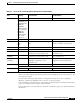
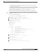
Step 3 Check the Input cells and Output cells fields. If the errors and the input and output difference exceed
0.5 to 2.0 percent of traffic on the interface, the interface is experiencing congestion and dropping cells.
Step 4 Check the AAL5 crc errors field. If the errors and the input and output difference exceed
0.5 to 2.0 percent of traffic on the interface, check for the following:
• Many CRC errors, but not many collisions. This indicates excessive noise.
• Cable damage. If you are using UTP cables, make sure you are using category 5 cables and not
another type, such as category 3.
If you determine that the physical interface is configured incorrectly, refer to the “Configuring
Interfaces” chapter in the ATM Switch Router Software Configuration Guide.