
Specifications

6 Input/Output Controller Replacement Instructions
Input/Output Controller Description
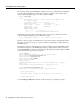
Table 2 lists the factory-installed Flash memory card options and their product numbers, and Table 3
lists the Flash Disk memory options and their product numbers.
Table 2 Flash Memory Card Options
Table 3 Flash Disk Memory Options
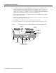
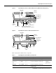
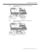
Depending on whether the Fast Ethernet port is present, up to five LEDs on the I/O controller
faceplate indicate system status; two additional LEDs indicate the status of the Flash Disk or Flash
memory cards installed in either PCMCIA slot.
Figure 4 shows the LEDs on the I/O controller with the Fast Ethernet port equipped with a single
MII receptacle. Figure 5 shows the LEDs on the I/O controller with the Fast Ethernet port that is
equipped with an MII receptacle and an RJ-45 receptacle. Figure 6 shows the LEDs on the I/O
controller without the Fast Ethernet port. Table 4 lists I/O controller LEDs and their functions.
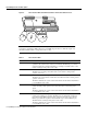
A CPU reset button is located next to the IO power OK LED or next to the auxiliary port on the I/O
controller faceplate. The CPU reset button resets the entire system.
Caution To prevent system errors and problems, use the CPU reset button only at the direction of
your service representative.
Memory Size
1
1 Refer to the Cisco AS5800 Universal Access Server documentation
listed in the “If You Need More Information” section on page 2, for
Cisco AS5800 Universal Access Server Flash memory card options.
Product Number
16 MB MEM-I/O-FLC16M
2
2 These products are also available as Flash card upgrades. To order an
upgrade, add an equal sign (=) after the product number, for example,
MEM-I/O-FLC16M=.
20 MB MEM-I/O-FLC20M
2
Memory Size Product Number
40 MB MEM-I/O-FLD40M
1
1 These products are also available as Flash Disk upgrades.
To order an upgrade, add an equal sign (=) after the product
number, for example, MEM-I/O-FLD110M=.
110 MB MEM-I/O-FLD110M