
Specifications

Input/Output Controller Replacement Instructions 5
Input/Output Controller Description
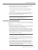
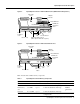
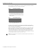
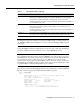
Figure 2 Input/Output Controller—with Fast Ethernet Port (MII and RJ-45 Receptacles)
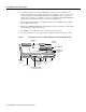
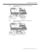
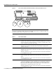
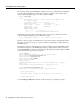
Figure 3 Input/Output Controller—without Fast Ethernet Port
Table 1 lists the I/O controller memory components.
Table 1 Input/Output Controller Memory Components
Type Size Quantity Description Location
Boot ROM 256 KB 1 EPROM for the ROM monitor program Socket U20
Flash SIMM
Flash memory
card
Flash Disk
8 MB
8 to 20 MB
40 or 110 MB
1
Up to 2
Up to 2
Contains the default boot helper image
Contains the default Cisco IOS image
Contains the default Cisco IOS image
Socket U99
PCMCIA
Slot 0 and slot
1
NVRAM 128 KB 1 Nonvolatile EPROM for the system
configuration file
Socket U41
H11293
AUX
CONSOLE
Midplane
connectors
Temperature
sensor
Flash SIMM U99
NVRAM U41
Temperature
sensor
Boot ROM U20
PC Card slots
Console
port
Captive
installation
screw
ENABLED
PCMCIA
EJECT
SLOT 0
SLOT 1
FE MII
FAST ETHERNET INPUT/OUTPUT CONTROLLER
LEDs CPU reset button
Auxiliary
port
RJ-45
CPU RESET
Optional Fast Ethernet port
(MII receptacle and RJ-45 receptacle)
MII
EN
RJ45
EN
RJ45
LINK
1O PWR
OK
H7400
AUX
CONSOLE
Midplane
connectors
Temperature
sensor
Flash SIMM U99
NVRAM U41
Temperature
sensor
Boot ROM U20
PC Card slots
Console
port
Captive
installation
screw
LED and
CPU reset
button
Auxiliary
port
ENABLED
PCMCIA
EJECT
SLOT 0
CPU RESET
1O POWER
OK
SLOT 1
INPUT/OUTPUT CONTROLLER