
Specifications

Input/Output Controller Replacement Instructions 45
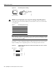
Installing and Removing a Flash Memory Card
Auxiliary Port Signals
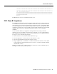
Table 9 lists the signals used on the auxiliary port. The auxiliary port supports hardware flow control
and modem control.
Table 9 Auxiliary Port Signals
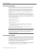
Installing and Removing a Flash Memory Card
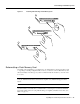
The I/O controller has two PCMCIA slots: slot 0 (lower) and slot 1 (upper). (See Figure 31.)
Note For procedures that explain how to remove and replace the PCMCIA Flash Disk, refer to the
Using the PCMCIA Flash Disk document that accompanies every Flash Disk shipped from the
factory.
Note To avoid potential problems when inserting spare Flash memory cards in your router, we
recommend that you reformat all of your Flash memory cards using the recommended minimum
Cisco IOS software release for your platform during your regularly scheduled service times. (See
Table 5 on page 12.)
The “Reformatting a Flash Memory Card” section on page 47, explains how to reformat a Flash
memory card.
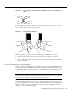
To install a Flash memory card in either PCMCIA slot, complete the following steps:
Step 1 Orient the Flash memory card so that its connector end faces the appropriate slot. (See
Figure 31a.)
Step 2 Carefully guide the card into the slot until it mates with the slot’s connector, and the eject
button for the slot pops out toward you. (See Figure 31b.)
Pin Signal Direction Description
2 TxD —> Transmit Data
3 RxD <— Receive Data
4 RTS —> Request To Send (used for hardware flow control)
5 CTS <— Clear To Send (used for hardware flow control)
6 DSR <— Data Set Ready
7 Signal Ground – Signal Ground
8 CD <— Carrier Detect (used for modem control)
20 DTR —> Data Terminal Ready (used for modem control only)