
Specifications

Input/Output Controller Replacement Instructions 31
Reconnecting Input Power and Powering Up the Router
Note Make sure the entire stripped end of each lead is inserted all the way into its
receptacle. If any exposed wire at the stripped end of a lead is visible after inserting the
lead into its receptacle, remove the lead from the receptacle, use the wire stripper to cut
the stripped end of the lead, and repeat Step 3 through Step 5.
Step 6 After tightening the receptacle screw or nuts for the ground, +48V, and –48V DC-input
leads, secure the leads to the power supply faceplate. For the Cisco 7200 series, use the
cable tie you saved earlier in this procedure to secure the three leads.
For the Cisco uBR7200 series, run the +48V and –48V leads between the two strain-relief
studs on the power supply faceplate. (See Figure 21.)
Note For the Cisco 7200 series routers, when securing the ground, +48V, and –48V
DC-input leads to the power supply faceplate, leave a small service loop in the ground
lead to ensure that it is the last lead to disconnect from the power supply if a great deal of
strain is placed on all three leads. (See Figure 20.)
A service loop is not required in the lead attached to the grounding lug on the
Cisco uBR7200 series router because this lead is separate from the +48V and –48V leads
and is secured by two M5 nuts to the M5 receptacles.
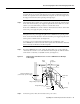
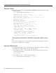
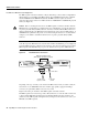
Step 7 For a Cisco uBR7200 series router, replace the strain-relief cover over the +48V and
–48V leads and secure the cover to the strain-relief studs using the two M4 nuts with the
7-mm wrench or nut driver (or adjustable wrench). (See Figure 23.)
Figure 23 Replacing the Strain-Relief Cover on a Cisco uBR7200 Series DC-Input
Power Supply
Step 8
Connect the ground, +48V, and –48V leads to the power source.
12523
Power
switch
Power
receptacle
Strain-relief
cover
M4 nuts
M5 grounding lug
Captive installation screw
(on both sides of power supply)
M5 grounding receptacles
+48V lead
-48V lead