
Specifications

Input/Output Controller Replacement Instructions 25
Replacing an Input/Output Controller
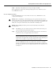
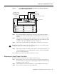
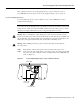
Figure 15 Cisco uBR7200 Series Input/Output Controller Ports, Handle, and Captive
Screws (Cisco uBR7246 Shown)
Step 4
Remove the Flash Disks or Flash memory cards (if present) from the I/O controller’s
PCMCIA slots. (See the “Installing and Removing a Flash Memory Card” section on
page 45.)
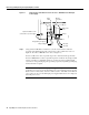
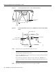
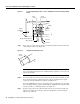
Step 5 Using a number 2 Phillips or a 3/16-inch, flat-blade screwdriver, loosen the two captive
installation screws on the faceplate of the I/O controller. (For a Cisco 7200 series router,
see Figure 14. For a Cisco uBR7200 series router, see Figure 15.)
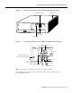
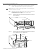
Step 6 Grasp the I/O controller handle and carefully pull the controller from its chassis slot.
Caution Handle the I/O controller by the carrier edges and handle only; never touch the printed
circuit board components or connector pins. (See Figure 7.)
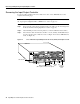
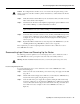
Step 7 Place the I/O controller on an antistatic surface with its components facing upward, or in
a static shielding bag. If you are returning the I/O controller to the factory, immediately
place it in a static shielding bag.
This completes the procedure for removing an installed I/O controller.
Replacing an Input/Output Controller
To install a new I/O controller in the router, complete the following steps:
Step 1 Ensure that the router is powered down and its input power cable is disconnected from
the router and the power source. (See the “Powering Down the Router and Disconnecting
Input Power” section on page 19.)
Step 2 Attach an ESD-preventive wrist strap between you and an unfinished chassis surface.
Step 3 Remove the I/O controller from its static shielding bag.
H11512
I/O controller
PCMCIA slots
Fast Ethernet port
(MII receptacle and
RJ-45 receptacle)
Handle
Auxiliary port
Console port
Captive installation screw (2)