
Specifications

22 Input/Output Controller Replacement Instructions
Removing and Replacing the Input/Output Controller
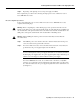
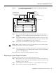
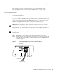
Figure 11 Removing the Strain-Relief Cover from a Cisco uBR7200 Series DC-Input
Power Supply
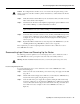
Step 3
Using a 3/16-inch flat-blade screwdriver, loosen the screw below the +48V lead
receptacle, and pull the lead from the connector (For a Cisco 7200 series router, see
Figure 12. For a Cisco uBR7200 series router, see Figure 13.)
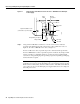
For Cisco 7200 series routers, repeat this step for the –48V lead and the ground lead.
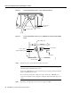
For Cisco uBR7200 series routers, repeat this step for the –48V lead only. Using an 8-mm
wrench or nut driver (or adjustable wrench) loosen and remove the two M5 nuts that
secure the two-hole grounding lug to the grounding receptacle, and pull the grounding lug
and lead from the receptacle.
Note The color coding of the DC-input power supply leads depends on the color coding
of the DC power source at your site. Typically, green or green/yellow is used for ground,
black is used for +48V (return), and red or white is used for –48V. Make certain the lead
color coding you choose for the DC-input power supply matches lead color coding used
at the DC power source.
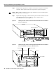
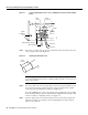
M5 grounding lug
+48V lead
-48V lead
12522
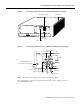
Power
switch
Power
receptacle
Captive installation screw
(on both sides of power supply)
Strain-relief
cover
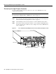
M4 nuts
M5 grounding receptacles