
Specifications
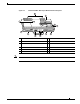
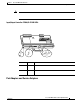

LED Descriptions
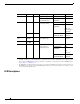
Type Size Quantity Memory Description Model Location
The C7200-I/O-GE+E and C7200-I/O-2FE/E do not have a boot ROM component.
256 KB 1 32-pin DIP-type C7200-I/O-FE-MII U20
32-pin DIP-type or
32-pin PLCC-type
C7200-I/O-FE,
C7200-I/O
U20 or U4
Flash memory 4 MB 1 Contains the default
boot helper image
C7200-I/O-FE-MII U99
C7200-I/O-FE,
C7200-I/O
U99
or
U10, U11,
U12, and U13
(soldered)
2
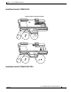
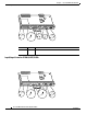
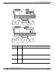
2. Some I/O controllers have no Flash SIMM but use a permanently soldered 4-MB or 8-MB Flash memory chip instead. (For
the location of the 4-MB Flash memory chip, see the Figure 1-18 and Figure 1-20. For the location of the 8-MB Flash memory
chip, see Figure 1-15 and Figure 1-16.)
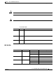
8 MB 1 C7200-I/O-GE+E,
C7200-I/O-2FE/E
U13 and U25
(soldered)
2
Flash memory
card
16 or
20 MB
Up to 2 Contains the default
Cisco IOS image
All models PC Card slot 0
and slot 1
Flash Disk 32, 48, or
128 MB
Up to 2
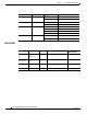
NVRAM 128 KB 1 Nonvolatile EPROM
for the system
configuration file
C7200-I/O-FE-MII U41
C7200-I/O-FE,
C7200-I/O
U41
or
U14
(soldered)
3
3. The NVRAM on some I/O controllers is replaced by a 32-pin nonsocketed SRAM component that is soldered onto the card.
The SRAM component is made to act like the NVRAM by the addition of some external components, one of which is a 1-inch
(2.54-cm) button-type lithium battery.
C7200-I/O-GE+E,
C7200-I/O-2FE/E
U19
(soldered)
3