
Installation guide


17-38
Cisco 10000 Series Routers Line Card Hardware Installation Guide
OL-6773-04
Chapter 17 Installing and Removing Line Cards
Attaching Cables
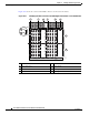
Figure 17-37 shows an overview of the BNC connectors on the rear of the chassis.
Figure 17-37 Identifying the BNC Connectors and Half-Height Card Subslots—Cisco 10008 Router
1 Line card slot 8 5 Line card slot 1
2 Line cards slot 5 6 Power supply
3 Blower module 7 Half-height line card subslot 0
4 Line card slot 4 8 Half-height line card subslot 1
1
26111
0
0
Tx
RX
Tx
RX
1
1
Tx
RX
Tx
RX
2
2
Tx
RX
Tx
RX
3
3
Tx
RX
Tx
RX
4
4
Tx
RX
Tx
RX
5
5
Tx
RX
Tx
RX
6
6
Tx
RX
Tx
RX
7
7
Tx
RX
Tx
RX
4 5
3
6
2
0
Tx
RX
1
7
8