
Installation guide


17-37
Cisco 10000 Series Routers Line Card Hardware Installation Guide
OL-6773-04
Chapter 17 Installing and Removing Line Cards
Attaching Cables
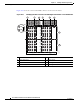
To attach the adapter cable for the 24-port channelized E1/T1 line card, follow these instructions:
Step 1 Connect an RJ-45 shielded twisted-pair (STP) cable to a port on the faceplate of the 24-port Channelized
E1/T1 line card (Figure 17-36).
Figure 17-36 Attaching the RJ-45 Port STP Cable to the Adapter Cable
Step 2 Connect the opposite end of the RJ-45 STP cable to the adapter cable as shown in Figure 17-36.
Go to the “Checking the Installation” section on page 17-58.
Attaching Coaxial Cables
If your line card uses the BNC connectors on the rear of the router, attach the cables as noted in the
specific line card overview chapter.
1 Adapter cable 3 Connecting cable (RJ-45 STP, male/male)
2 RJ-45 ports on faceplate
2
1
3
RJ-48c
CONNNECT XMIT SHIELD TO GND 12
12
DISCONNNECT XMIT SHIELD TO GND 12
X
MIT
RCV
CISCO
10000
FAIL
11
10
1
126772