2012 DATA SWITCH DS74 COPYRIGHT 2012 Bay Technical Associates, Inc 12/1/2012
Table of Contents COMPLIANCE STANDARD .............................................................................................................................................................. 4 CONNECTION DESCRIPTION ........................................................................................................................................................... 5 INSTALLATION .......................................................................................................................
DS74 (4) EIA232 Serial Port Module Page 3 DS6 IPS
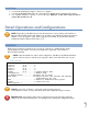
ABOUT THIS DS74 OWNER’S MANUAL This document is applicable to the DS74 (4) EIA 232 Serial Port Module. This document provides information required for installing and operating your Bay Tech equipment. It should allow the user to connect to, power up, and access an applications menu where peripheral equipment can be controlled. We recommend reading this manual carefully, while placing special emphasis on correct cabling and configuration.
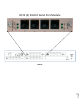
We welcome any comments you may have about our products, and we hope that you will continue to look to BayTech for your remote management needs. CONNECTION DESCRIPTION BayTech's DS74 serial module provides an interface to communicate to other devices with a serial console port. An RJ45–RJ45 cable or RJ45-RJ45 cable with RJ45–9 pin adapter is needed to connect to the devices. The DS74 is part of a Data Switch chassis and Host module systems. The DS74 ports are not standard pin outs.
CAUTION: This unit is intended for indoor use only. Do not install near water or expose this unit to moisture. To prevent heat buildup, do not coil the power cord when in use. Do not use extension cords. Do not attempt to make any internal changes to the power source. Do not attempt to modify any portion or component of DS Series Unit unless specifically directed to by BayTech personnel. BayTech must perform any internal operations. ATTENTION: Cette unité est prévue pour l'usage d'intérieur seulement.
CABLING RJ45 Cable Control Module RJ-45 pin Signals EIA 232 Signal Pin Signal Direction 1 2 DTR GND Out 3 4 5 6 7 8 RTS TX RX DSR GND CTS Out Out In In In Description Handshake, Line Driver Inactive State = Low: -12V when port is selected unless programmed differently. Used as a handshake line to enable/disable the receiving of characters.
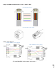
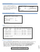
Sample: RJ08X007 Standard Rollover Cable – RJ45 to RJ45 Serial 2: RJ08X007 Pin out Serial 3: RJ45 Receptacle & Plug Sample 9-pin Adapters Serial 4: 9FRJ45PC-1 Adapter Pin Out Serial 5: 9FRJ45PC-4 Adapter Pin out Page 8 (Use with RJ08X007 Cable and B/C switch in “B”)
Serial Setup Connect the 9FRJ45PC-4 adapter to the user’s computer Connect the MODULE EIA-232 port to the adapter via the RJ08X007 rolled flat ribbon cable. Use terminal emulation software to access the unit, 9600 bps, 8 data bits, 1stop bit and no parity, B/C switch set to ‘B’. Detail Operations and Configurations NOTE: Depending on the DS-Series model, the menus may vary according to the number of DS74 modules installed in the unit.
CONFIGURATION MENU: 1st level of configuration identifies all modules connected to the DS-chassis. The DS74 has the (4) serial ports, May have more than one DS74 listed. DS-RPC are chassis with (4) power outlets. Menu 2: Module Configuration Module Configuration DS71-MD4 (2)..........1 Host Module DS74 (3)..........2 I/O EIA232 ports DS74 (4)..........2 I/O EIA232 ports DS-RPC (5)..........3 DS-RPC Chassis ONLY Exit......................
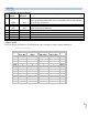
Menu 4: Serial Port Configuration +----+------+-----------------+------+------+------+------+---------+----+----+ |Port|Device| Device | Baud | Word | Stop |Parity|Handshake|LineDrive| | | Type | Name | Rate | Size | Bits | | |DTR |RTS | +----+------+-----------------+------+------+------+------+---------+----+----+ | 1 | RS232| Device A | 9600 | 8 | 1 | None | None | HI | HI | +----+------+-----------------+------+------+------+------+---------+----+----+ Handshaking......................1 Baud Rate.......
Set Baud Rate Select 2), from the Serial Port Configuration Menu changes the transfer rate of Data bits per second for the serial port, Default is 9600 Word Size Select baud rate: 1 For 300 2 For 600 3 For 1200 4 For 2400 5 For 4800 6 For 9600 7 For 19200 8 For 38400 9 For 57.6K A For 76.8K B For 115.2K Enter Request : The word size is the measurement of the actual data bits in a transmission. Which setting you choose depends on what information you are transferring.
Select 5), from the Serial Port Configuration Menu selects the Parity, Default is None Select parity: 1 For None 2 For Even 3 For Odd Enter Request : RTS/DTR Line Driver Inactivity State RTS (Request to Send)/ DTR (Data Terminal Ready) is normally used in conjunction with an external modem. With no modem the RTS and DTS default state is High.
Select 1, allows serial information to pass but prevents SNMP information from passing through. Select 2, enables the SNMP information to pass through along with serial data. Select either option. The module displays the DS74 Configuration menu. NOTE: Once you make a change to the port type, you have to back out of the Port Type menu and will be asked to ‘Accept changes’. If you type ‘Y’ for YES, the changes take effect immediately for the serial port. Type “Y” to accept changes and press ‘Enter’.
BAYTECH PRODUCT WARRANTY Bay Technical Associates (BayTech) warrants that its products will be free from defects in materials and workmanship under normal use for a period of two years from date of purchase (or from date of shipment from BayTech if proof of purchase is not provided). During this warranty period, BayTech shall, at its discretion, either repair or exchange any defective product at no charge for labor and materials, or refund the amount paid for the product, less shipping and handling charges.
Technical Support BayTech offers Tech Support for the lifetime of the product. A staff of Applications Engineers is on duty to assist with installation, set up or operation issues. Support is available from 8:00 a.m. to 5 p.m. (CST or CDT), Monday through Friday at the phone numbers or website provided below.
Return Authorization Process: a. Contact BayTech via Phone, Fax, or Email to get a Return Authorization (RA) Number. IMPORTANT: BayTech will not accept any returns without an RA number. b. Package the unit carefully in its original packaging or similar packaging. The warranty does not cover damage sustained during shipment. Enclose a letter with name, address, RA number, daytime phone number and description of the problem. c. Mark the RA number clearly on the outside of the package. d.