CH A P T E R 11 Cisco ASR 1001 Router Overview and Installation This chapter describes the Cisco ASR 1001 Router and provides procedures for installing the Cisco ASR 1001 Router on an equipment shelf or tabletop or in an equipment rack.
Chapter 11 Cisco ASR 1001 Router Overview and Installation Cisco ASR 1001 Router Description The Cisco ASR 1001 Router supports: • ESP bandwidth 2.
Chapter 11 Cisco ASR 1001 Router Overview and Installation Cisco ASR 1001 Router Description IDC-HD80G can support a single 2.5-inch SATA HDD/SSD (see Figure 11-1).
Chapter 11 Cisco ASR 1001 Router Overview and Installation Cisco ASR 1001 Router Description • IDC-OC3POS IDC-OC3POS can support two channels of OC3 (see Figure 11-2).
Chapter 11 Cisco ASR 1001 Router Overview and Installation Cisco ASR 1001 Router Description • IDC-4XGE IDC-4XGE can support up to four small form-factor pluggable (SFP) transceivers, each of which supports a 1-Gigabit Ethernet connection (see Figure 11-3).
Chapter 11 Cisco ASR 1001 Router Overview and Installation Cisco ASR 1001 Router Description • IDC-CHT1/E1 IDC-CHT1/E1 can support eight ports of fully channelized T1 or E1 interfaces (see Figure 11-4).
Chapter 11 Cisco ASR 1001 Router Overview and Installation Cisco ASR 1001 Router Description • IDC-4XT3 IDC-4XT3 can support up to four unchannelized DS3 (44.736 Mbps) ports (see Figure 11-5).
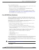
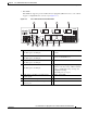
Chapter 11 Cisco ASR 1001 Router Overview and Installation Cisco ASR 1001 Router Description The following figures show the front panel of the Cisco ASR 1001 Router with the various IDCs. Figure 11-6 shows the LEDs that are common to all configurations of the Cisco ASR 1001 Router.
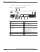
Chapter 11 Cisco ASR 1001 Router Overview and Installation Cisco ASR 1001 Router Description Cisco ASR 1001 Router Faceplate Common Components The Cisco ASR 1001 Router RP faceplate has common components for each type of ASR 1001 Router configuration. Figure 11-6 and Figure 11-7 show the Cisco ASR1000-RP faceplate with LEDs and connectors for all configurations of the Cisco ASR 1001 Router.
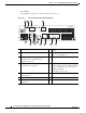
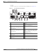
Chapter 11 Cisco ASR 1001 Router Overview and Installation Cisco ASR 1001 Router Description Cisco ASR 1001 Chassis Front View Figure 11-8 shows the front of the Cisco ASR 1001 Router.
Chapter 11 Cisco ASR 1001 Router Overview and Installation Cisco ASR 1001 Router Description Seven internal fans draw cooling air into the chassis and across internal components to maintain an acceptable operating temperature. The fans are located at the rear of the chassis. A two-hole grounding lug is located on the side of the chassis. Each individual fan also has a fan fail status signal. The fan fail signal is asserted if the fan speed falls below 50% of the rated speed.
Chapter 11 Cisco ASR 1001 Router Overview and Installation Cisco ASR 1001 Router Description The main components of the Cisco ASR 1001 Router, ASR1000-RP1, ASR1000-ESP5, and ASR1000-SIP10 are fixed in the chassis and are not upgradeable, except for the power supplies and SPAs. Cisco Embedded ASR1000-RP1 for Cisco ASR 1001 Router Description The Cisco ASR 1000 Series route processor (embedded for the Cisco ASR 1001 Router) is the central control processor and runs the network operating system.
Chapter 11 Cisco ASR 1001 Router Overview and Installation Cisco ASR 1001 Router Description Cisco Embedded ASR1000-SIP10 and SPAs for the Cisco ASR 1001 Router Description The Cisco embedded ASR1000-SIP10 is built into the Cisco ASR 1001 Router. The Cisco embedded ASR1000-SIP10 provides the physical and electrical termination for up to three SPAs, built-in 4xGE SPA, one half-height SPA bay, and one integrated daughter card (system configurable).
Chapter 11 Cisco ASR 1001 Router Overview and Installation Cisco ASR 1001 Router Description Table 11-4 Cisco ASR 1001 LEDs No. LED Label LED Color Behavior Description 1 PWR Power Solid green All power supplies are within operational limits. Off Off. The router is in standby mode. 2 ACTV Active Green The embedded services processor is green when active. 3 STAT STATUS Green Code has downloaded successfully and is operational. Yellow BOOT ROM has loaded successfully.
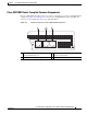
Chapter 11 Cisco ASR 1001 Router Overview and Installation Cisco ASR 1001 Router Description AC Power Supply for Cisco ASR 1001 Router The AC power supply input inlet is an IEC connector. The current rating on the connector is 10 A. The AC power supply is secured into the chassis with two captive screws mounted on the faceplate. Figure 11-11 shows the AC power supply for the Cisco ASR 1001 Router.
Chapter 11 Cisco ASR 1001 Router Overview and Installation Installation Methods Table 11-5 –48 VDC Power Supply Output Voltage Alarm Threshold Ranges Output Minimum Maximum 12V 10.0-11.2V 12.8-13.8V 3.3V 2.6 - 3.0 V None Power Cords Supported by the Cisco ASR 1001 Router Table 11-6 lists the power cords that are supported by the Cisco ASR 1001 Router.
Chapter 11 Cisco ASR 1001 Router Overview and Installation General Rack Installation Guidelines Note You have already unpacked your chassis and read all the site requirements for your new equipment. Proceed with the installation. General Rack Installation Guidelines When planning your rack installation, consider the following guidelines: Caution • The Cisco ASR 1001 Router requires a minimum of 3.5 inches or 8.9 cm rack units of vertical rack space.
Chapter 11 Cisco ASR 1001 Router Overview and Installation Guidelines for an Equipment Shelf or Tabletop Installation Table 11-7 Cisco ASR 1001 Router Dimensions and Weight Cisco ASR 1001 Dimensions Width 17.25 in. (43.815 cm) - 19 inch rack-mount Weight 40 lb (18.143 k) - fully configured Guidelines for an Equipment Shelf or Tabletop Installation The chassis should already be in the area where you will install it.
Chapter 11 Cisco ASR 1001 Router Overview and Installation Mounting the Cisco ASR 1001 Router on an Equipment Shelf or Tabletop Installation Step 3 Attach the front rack-mount brackets. Locate the threaded holes in the front sides of the chassis (first holes beyond the vent holes) and use the package of black screws that shipped with the chassis. Step 4 Align the front rack-mount bracket to one side of the chassis. Step 5 Insert and tighten the screws on one side.
Chapter 11 Cisco ASR 1001 Router Overview and Installation Rack-Mounting the Cisco ASR 1001 Router Rack-Mounting the Cisco ASR 1001 Router The Cisco ASR 1001 Router can be installed in an existing rack with equipment or in an empty rack with no equipment: The chassis can be mounted in either rack types: • Two-post rack, either 19 inch or 23 inch. Inner clearance (the width between the inner sides of the two posts or rails) must be at least 19 inches (48.26 cm). The height of the chassis is 3.
Chapter 11 Cisco ASR 1001 Router Overview and Installation Attaching the Chassis Rack-Mount Brackets Step 2 Measure the space between the inner edges of the left front and right front mounting flanges on the equipment rack. The space must be at least 17.7 inches (45 cm) to accommodate the chassis which is 17.25 inches (43.8 cm) wide and fits between the mounting posts on the rack. Attaching the Chassis Rack-Mount Brackets This section explains how to attach the front rack-mount brackets to the chassis.
Chapter 11 Cisco ASR 1001 Router Overview and Installation Installing the Cisco ASR 1001 Router in a Rack Figure 11-15 shows where to attach the front rack-mount brackets to the Cisco ASR 1001 Router.
Chapter 11 Cisco ASR 1001 Router Overview and Installation Installing the Cisco ASR 1001 Router in a Rack Step 2 Make sure that your path to the rack is unobstructed. If the rack is on wheels, ensure that the brakes are engaged or that the rack is otherwise stabilized. See the next sections on the types of racks you can use to install the chassis. Step 3 (Optional) Install a shelf in the rack to support the Cisco ASR 1001 Router.
Chapter 11 Cisco ASR 1001 Router Overview and Installation Installing the Cisco ASR 1001 Router in a Rack Two-Post Rack Installation The Cisco ASR 1001 Router can be installed on a two-post rack, either 19 inch or 23 inch. Note Caution Step 1 Inner clearance (the width between the inner sides of the two posts or rails) must be at least 19 inches (48.26 cm). The height of the chassis is 1.71 inches (43.43 mm). Airflow through the chassis is from front to back.
Chapter 11 Cisco ASR 1001 Router Overview and Installation Installing the Cisco ASR 1001 Router in a Rack Four-Post Rack Installation The Cisco ASR 1001 Router can be flush-mounted in a 19-inch equipment rack using the rack-mounting kit provided with your system. The Cisco ASR 1001 Router can be mounted into the rack using two recommended methods: • Installing the chassis in an existing rack with equipment. • Installing an empty chassis in a rack with no equipment installed.
Chapter 11 Cisco ASR 1001 Router Overview and Installation Attaching the Cable-Management Bracket Figure 11-17 shows front and rear rack-mounting of the Cisco ASR 1001 Router on a four-post rack. Cisco ASR 1001 Router in a Four Post Rack—Front and Rear Rack-Mounting 279913 Figure 11-17 Step 6 Use a level to verify that the tops of the two brackets are level, or use a measuring tape to verify that both brackets are the same distance from the top of the rack rails.
Chapter 11 Cisco ASR 1001 Router Overview and Installation Attaching a Chassis Ground Connection Step 1 Align the cable-management bracket to the rack-mount bracket on one side of the Cisco ASR 1001 Router. The cable-management bracket aligns to the top hole of the chassis rack-mount bracket. Step 2 Using a Phillips screwdriver, insert the screw through cable-management bracket and into the chassis rack-mount and tighten the screw.
Chapter 11 Cisco ASR 1001 Router Overview and Installation Attaching a Chassis Ground Connection Recommended Tools and Supplies The following tools, equipment, and supplies necessary to connect the system ground to the chassis: • Phillips screwdriver • 3.5 mm flat blade screwdriver (Phoenix # 1205053 or equivalent 3.5 mm flat blade) • Dual-lug chassis ground component • Grounding wire Figure 11-19 shows how to attach the ground lugs on the Cisco ASR 1000 Series chassis.
Chapter 11 Cisco ASR 1001 Router Overview and Installation Attaching a Chassis Ground Connection Caution The grounding wire is always the first to be installed or connected and the last to be removed or disconnected. Use the following procedure to attach the grounding lug to the chassis ground connector on your chassis: Step 1 Use the wire stripper to strip one end of the AWG #6 wire approximately 0.75 inches (19.05 mm). Step 2 Insert the AWG #6 wire into the wire receptacle on the grounding lug.
Chapter 11 Cisco ASR 1001 Router Overview and Installation Connecting the Shared Port Adapter Cables Connecting the Shared Port Adapter Cables The instructions for connecting the cables for the shared port adapter installed in the Cisco ASR 1001 Router are contained in the respective configuration documents for each port adapter.
Chapter 11 Cisco ASR 1001 Router Overview and Installation Connecting a Terminal to the Cisco ASR1000-RP1 Console Port Step 2 Insert the other end of the RJ-45 cable to your management device or network. Connecting a Terminal to the Cisco ASR1000-RP1 Console Port The Cisco ASR 1001 embedded route processor has an asynchronous serial (EIA/TIA-232) RJ-45 console port labeled CON on its front panel.
Chapter 11 Cisco ASR 1001 Router Overview and Installation Auxiliary Connection • Verify all cabling limitations (particularly distance) before powering on the system. Auxiliary Connection This asynchronous EIA/TIA-232 serial port (AUX) is used to connect a modem to the Cisco ASR 1000 Series Route Processor 1 for remote administrative access. Use the following procedure to connect the Cisco ASR 1001 Router to a modem.
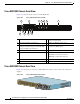
Chapter 11 Cisco ASR 1001 Router Overview and Installation Cisco ASR 1001 Router Power Supply Installation Note The Cisco ASR 1001 Router can support two AC or two DC power supplies. Do not mix AC and DC power supply units in the same chassis. Figure 11-21 shows both the AC and DC power supplies for the Cisco ASR 1001 Router.
Chapter 11 Cisco ASR 1001 Router Overview and Installation Cisco ASR 1001 Router Power Supply Installation This section contains the following topics: • Installing AC Input Power to Cisco ASR 1001 Router, page 11-350 • Removing AC Power Supply from the Cisco ASR 1001 Router, page 11-352 • Installing DC Input Power on the Cisco ASR 1001 Router, page 11-354 • Removing DC Input Power from the Cisco ASR 1001 Router, page 11-359 Warning The covers are an integral part of the safety design of the prod
Chapter 11 Cisco ASR 1001 Router Overview and Installation Cisco ASR 1001 Router Power Supply Installation Figure 11-23 shows the Cisco ASR 1001 Router AC power supply standby switch. Cisco ASR 1001 Router AC Power Supply Standby Switch 207695 Figure 11-23 1 1 Cisco ASR 1001 Router Standby switch, which does not disconnect power from the power source. Step 2 Turn off the circuit breaker to the power supply.
Chapter 11 Cisco ASR 1001 Router Overview and Installation Cisco ASR 1001 Router Power Supply Installation Step 5 Make certain that the AC power cords are positioned as shown in Figure 11-24. Correct Position of the Cisco ASR 1001 Router AC Power Supply Cables 207697 Figure 11-24 1 3 2 1 AC power supply in PS0 3 2 Position of power supply cable from PS0 — — AC power supply in PS1 Step 6 Plug the AC power supply cables into the AC power source. Step 7 Turn on the AC breaker.
Chapter 11 Cisco ASR 1001 Router Overview and Installation Cisco ASR 1001 Router Power Supply Installation Step 2 To remove the power cord from PS1, position the power supply cable in order to access the power supply fasteners. Hold back the power supply cable in PS0, as shown in Figure 11-25, ensuring that you do not unplug the power cable.
Chapter 11 Cisco ASR 1001 Router Overview and Installation Cisco ASR 1001 Router Power Supply Installation Installing DC Input Power on the Cisco ASR 1001 Router The Cisco ASR 1001 Router DC input connector is compatible with a pluggable Euro-style plug. The input connector and plug must be UL recognized under UL 486 for field wiring. The connection polarity shall be from left to right: negative (–), positive (+), and ground. See Figure 11-21.
Chapter 11 Cisco ASR 1001 Router Overview and Installation Cisco ASR 1001 Router Power Supply Installation Step 3 Turn off the circuit breaker to the power supply. Wiring the DC Input Power Source The Cisco ASR 1001 Router DC power supply has a connector plug that is installed into the power supply terminal block header.
Chapter 11 Cisco ASR 1001 Router Overview and Installation Cisco ASR 1001 Router Power Supply Installation Use the information provided in this section to wire the DC input power source: Step 1 At the front of the router, ensure that the power switch is in the Standby position. Step 2 Move the circuit-breaker switch handle to the Off position, and apply tape to hold it in the Off position. Step 3 Gather the DC power supply terminal block plug.
Chapter 11 Cisco ASR 1001 Router Overview and Installation Cisco ASR 1001 Router Power Supply Installation Figure 11-30 shows the DC power supply with lead wires. Figure 11-30 DC Power Supply with Lead Wires 1 2 207765 3 1 Negative (–) lead wire 3 2 Positive (+) lead wire — — Ground lead wire Step 7 Insert the exposed wire of one of the ground wire into the terminal block plug. Ensure that you cannot see any wire lead. Only wires with insulation should extend from the terminal block.
Chapter 11 Cisco ASR 1001 Router Overview and Installation Cisco ASR 1001 Router Power Supply Installation Step 8 Use a ratcheting torque screwdriver to torque the terminal block plug captive screw (above the installed wire lead) to from 0.5 Nm (4.425 lbf in. to 0.6 Nm (5.310 lbf in.), as shown in Figure 11-31. Figure 11-31 Torquing the DC Power Supply Terminal Block Plug Screws 207764 1 1 Step 9 Torque is from 0.5 Nm (4.425 lbf in.) to 0.6 Nm (5.310 lbf in.
Chapter 11 Cisco ASR 1001 Router Overview and Installation Cisco ASR 1001 Router Power Supply Installation Caution Step 10 Secure the wires coming in from the terminal block plug so that they cannot be disturbed by casual contact. Use a tie wrap to secure the wires to the rack, so that the wires are not pulled from the terminal block plug by casual contact. Make sure the tie wrap allows for some slack in the ground wire. Figure 11-33 shows the DC terminal block plug inserted and the tie wrap secured.
Chapter 11 Cisco ASR 1001 Router Overview and Installation Cisco ASR 1001 Router Power Supply Installation Step 4 Grasping the power supply handle with one hand, pull the power supply out of the chassis while supporting it with the other hand. This completes the procedure for removing the DC power supply from the Cisco ASR 1001 Router.