
Installation guide


4-24
Cisco ASA 5500-X Series Hardware Installation Guide
OL-32129-01
Chapter 4 Maintenance and Upgrade Procedures for the ASA 5500-X
Install and Remove a Solid State Drive for a Services Module
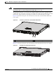
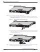
Figure 4-32 Removing an SSD from the ASA 5545-X and ASA 5555-X
Step 2
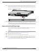
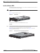
To install an SSD, on the front panel of the chassis, line up the SSD carrier with the SSD bay and push it
in until it is seated. Push the locking lever into place.
Figure 4-33 shows the ASA 5512/5515/5525-X models, while Figure 4-34 shows the
ASA 5545/5555-X models.
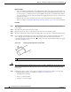
Figure 4-33 Installing an SSD in the ASA 5512/5515/5525-X
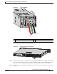
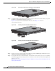
Figure 4-34 Installing an SSD in the ASA 5545-X and ASA 5555-X
Step 3
On the front panel of the ASA, make sure the HDD1 (top SSD) and HDD0 (bottom SSD) indicators are
solid green to indicate that the SSDs are now active.
Step 4 If you replaced the drive in the ASA 5512-X, ASA 5515-X, or ASA 5525-X, you need to re-install the
module using appropriate boot image. For more information, refer to the list of ASA-related Quick Start
guides on cisco.com:
http://www.cisco.com/c/en/us/support/security/asa-5500-series-next-generation-firewalls/products-inst
allation-guides-list.html
334566
334634
334565