
Installation guide

4-11
Cisco ASA 5500-X Series Hardware Installation Guide
OL-32129-01
Chapter 4 Maintenance and Upgrade Procedures for the ASA 5500-X
Install and Remove SFP Modules
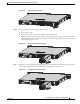
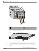
Step 11 Close the green connector clamp.
Step 12 Install the chassis cover, and replace the chassis in the rack.
Step 13 Install the power cable, and restore power to the chassis. The LEDs will blink when traffic begins to pass.
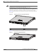
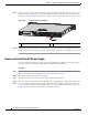
Install and Remove SFP Modules
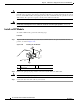
The ASA uses a small form-factor pluggable (SFP) module to establish Gigabit Ethernet connections;
this module is a hot-swappable input/output device that plugs into available SFP ports.
• SFP Module Support, page 4-11
• Install an SFP Module, page 4-12
• Remove the SFP Module, page 4-13
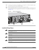
SFP Module Support
Table 4-1 lists the supported SFP modules.
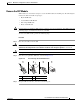
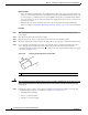
The 1000BASE-LX/LH and 1000BASE-SX SFP modules are used to establish fiber-optic connections.
Use fiber-optic cables with LC connectors to connect to an SFP module. The SFP modules support 850
to 1550 nm nominal wavelengths. The cables must not exceed the required cable length for reliable
communications. Table 4-2 lists the cable length requirements.
Use only Cisco certified SFP modules on the ASA. Each SFP module has an internal serial EEPROM
that is encoded with security information. This encoding provides a way for Cisco to identify and
validate that the SFP module meets the requirements for the ASA.
Table 4-1 Supported SFP Modules
SFP Module Type of Connection Cisco Part Number
1000BASE-LX/LH Fiber-optic GLC-LH-SM=
1000BASE-SX Fiber-optic GLC-SX-MM=
Table 4-2 Cabling Requirements for Fiber-Optic SFP Modules
SFP
Module
62.5/125 micron
Multimode 850
nm
Fiber
50/125 micron
Multimode 850
nm Fiber
62.5/125 micron
Multimode 1310
nm Fiber
50/125 micron
Multimode 1310
nm Fiber
9/125 micron
Single-mode
1310 nm Fiber
LX/LH — — 550 m at
500 Mhz-km
550 m at
400 Mhz-km
10 km
SX 275 m at
200 Mhz-km
550 m at
500 Mhz-km
———