
Installation guide

1-13
Cisco ASA 5500-X Series Hardware Installation Guide
OL-32129-01
Chapter 1 About the ASA 5500-X
ASA Chassis Panels
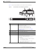
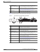
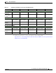
Figure 1-6 shows the rear panel ports for the ASA 5545-X and ASA 5555-X.
Figure 1-6 Rear Panel Ports for the ASA 5545-X and ASA 5555-X
3 GigabitEthernet data
interfaces (0/0 through 0/7)
The 8 on-board data interfaces. Connect with an RJ-45 cable.
The top row port numbers are (from left to right) 7, 5, 3, 1.
The bottom row port numbers are (from left to right) 6, 4, 2, 0.
4 USB Ports The two USB standard ports.
(See Internal and External USB Flash Drives, page 1-3.)
5 Console port The RS-232 serial console port used to directly connect a computer
to the ASA. Connect with an RJ-45 cable.
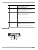
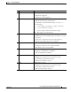
LED Description
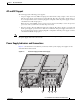
1 I/O slot Slot for the optional I/O Card. If you have a fiber-optic I/O card, use
SFP modules to connect (not included).
2 Thumbscrew The screw that tightens and loosens the chassis cover.
3 Management 0/0 interface The GigabitEthernet interface that is restricted to management use
only. Connect with an RJ-45 cable.
4 GigabitEthernet data
interfaces (0/0 through 0/7)
The 8 on-board data interfaces. Connect with an RJ-45 cable.
The top row port numbers are (from left to right) 7, 5, 3, 1.
The bottom row port numbers are (from left to right) 6, 4, 2, 0.
5 Power supplies Slots for the primary power supply that ships with the device, and
the optional redundant power supply.
6 USB ports The two USB standard ports.
(See Internal and External USB Flash Drives, page 1-3.)
7 Console port The RS-232 serial console port used to directly connect a computer
to the ASA. Connect with an RJ-45 cable.
8 Rear panel LEDs Rear panel LEDs. (See Figure 1-3 on page 1-10 for more
information.)
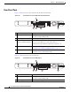
POWER
ALARMv
BOOT
ACTIVE
VPN
HD
282362
21 3
678
4 5