
Installation guide


A-4
Cisco 860 Series, Cisco 880 Series, and Cisco 890 Series Integrated Services Routers Hardware Installation Guide
OL-16215-10
Appendix A Technical Specifications
Console and Auxiliary Port Connector Pinouts
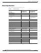
Table A-4 describes the RJ-45 connector pinouts for the Gigabit Ethernet (GE) ports of the Cisco
860VAE and 860VAE-K9 ISRs.
Console and Auxiliary Port Connector Pinouts
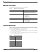
Table A-5 lists the pinouts for the console and auxiliary port connectors.
1. RX = Receive
2. TX = Transmit
Ta b l e A-4 Ethernet GE Port Pinouts
Pin
GE Signal
(LAN and WAN)
1 Tx A+
1
1. TX = Transmit
2 Tx A-
3 Rx B+
2
2. RX = Receive
4 Tx C+
5 Tx C-
6 Rx B-
7 Rx D+
8 Rx D-
Ta b l e A-5 Console and Auxiliary Port Connector Pinouts
RJ-45 Pin Function
1 RTS
2 DTR
3 TXD
4 GND
5 GND
6 RXD
7 DSR
8 CTS